Compressor and manufacturing method thereof

A manufacturing method and compressor technology, which are applied in the direction of mechanical equipment, machine/engine, and process efficiency improvement, etc., can solve the problems of easy deformation due to heat, tilting of the crankshaft, shortening the service life of the motor, etc., to solve the problem of stator and rotor clearance, The effect of improving assembly accuracy and meeting welding requirements

Inactive Publication Date: 2016-04-06
SHANGHAI HITACHI ELECTRICAL APPLIANCES CO LTD
View PDF5 Cites 7 Cited by
  • Summary
  • Abstract
  • Description
  • Claims
  • Application Information

AI Technical Summary

Problems solved by technology

The crankshaft 31' is relatively thin, resulting in an increase in the surface pressure of the upper bearing 4', local working conditions are relatively harsh, and wear is serious
In addition, especially in the case of improper welding of the upper bearing 4' and the sealing shell 2', the axis of the crankshaft may be inclined, and even a small inclination angle may cause wear to concentrate between the upper bearing 4' and the crankshaft 31'
[0009] (2) The welding of the sealed casing 2' and the upper cover 1' and the lower cover 7' may easily cause the deformation of the sealed casing 2'
Since the sealed casing 2' is generally a cylindrical structure, it is easily deformed when it is welded with the upper cover 1' and the lower cover 7'. This not only affects the overall airtightness of the compressor, but also causes the motor to The gap between the rotor and the stator is uneven, which will affect the overall coaxiality of the motor and the crankshaft, bearing parts, cylinder, etc., and reduce the working efficiency and performance of the compressor
[0010] (3) The gap between the inner rotor 32' and the outer stator 33' is poor
The rolling rotor compressors in the prior art are affected by the machining accuracy of parts and the positioning reference of the stator and rotor, so it has not been able to eliminate the problem of bad stator and rotor clearance from the root.
Since the upper bearing 4' is installed in the sealed casing 2', the coaxiality between the bearing surface of the upper bearing 4' itself and the inner wall of the sealed casing 2' is difficult to ensure, and the processing of the upper bearing 4' is extremely difficult.
The outer stator 33' is positioned based on the sealed casing 2'; the inner rotor 32' is positioned based on the crankshaft 31', and the crankshaft 31' is positioned based on the upper bearing 4', so when the upper bearing 4' and the sealed casing 2' are simultaneously When the axiality is not up to standard, the gap between the inner rotor 32' and the outer stator 33' will become very poor, and even cause wear between the inner rotor 32' and the outer stator 33', shorten the service life of the motor, and cause make a lot of noise

Method used


Image

  • Compressor and manufacturing method thereof
  • Compressor and manufacturing method thereof
  • Compressor and manufacturing method thereof

Examples


no. 1 example

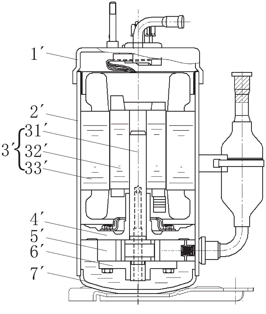
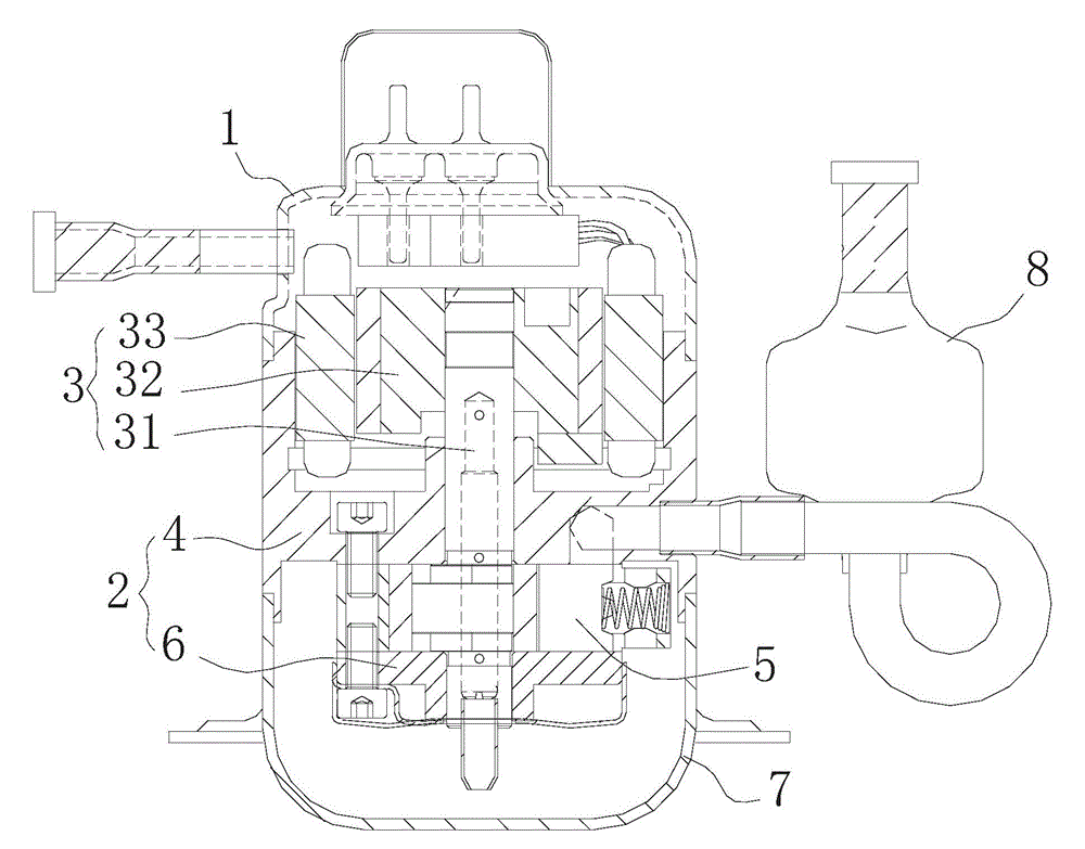
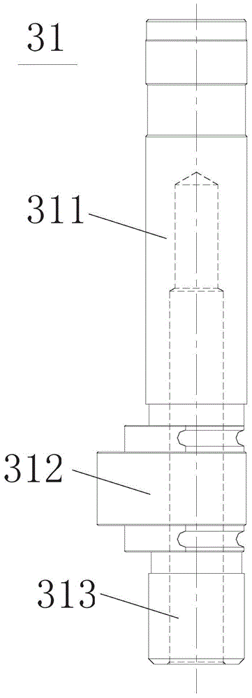
[0070] like figure 2 and image 3 As shown, the compressor of the present invention includes: a housing; the motor 3 is accommodated in the upper space in the housing; the cylinder 5 is accommodated in the lower space in the housing; the crankshaft 31 has a long axis portion 311 and an eccentric portion 312 and short axis portion 313 (such as image 3 As shown), the rotational force of the motor 3 is transmitted to the cylinder 5 to compress the refrigerant; the frame 2 is fixedly connected to the housing by welding; wherein, the frame 2 includes an upper bearing 4 and a lower bearing 6 (due to the present embodiment Take the vertical micro compressor as an example, so the upper bearing 4 is the main bearing, and the lower bearing 6 is the auxiliary bearing), the upper bearing 4, the lower bearing 6 and the cylinder 5 jointly define a compression space and have a support crankshaft 31 respectively Inner hole 44 (see Figure 4 ) and 61 (see Figure 5 ); the upper bearing 4...

no. 2 example

[0080] like Figure 7 As shown, in a modification example, the upper bearing 4a can also be a disc portion 41a with an inner hole 44a and an outer edge portion extending up and down from the outer edge of the disc portion 41a, and the middle cross-section of the upper bearing 4a as a whole is H shape. and Figure 4 and 5 The difference is that if Figure 7 The inner edge portion 45 of the upper bearing 4 is canceled in the upper bearing 4a. After canceling the inner edge part 45, the main part of the upper bearing 4a becomes a simple planar structure (disk part), and the processing becomes easier. Compared with the first embodiment, the inventors have found that: due to the cancellation of the inner edge portion 45, the difference between the inner diameter of the outer edge portion of the compressor of this embodiment and the diameter of the inner hole is smaller than that of a common compressor, and the outer edge portion itself The wall is also relatively thin, so that...


PUM

PropertyMeasurementUnit
thicknessaaaaaaaaaa

Abstract

The invention provides a compressor and a manufacturing method thereof. The compressor comprises a shell; a motor and a cylinder, which are accommodated in the shell; a crankshaft, which is used for transmitting the rotary force of the motor to the cylinder to compress a refrigerant; and a frame, which is fixedly connected with the shell through welding and comprises a main bearing and an auxiliary bearing, wherein the main bearing and the auxiliary bearing define a compression space together with the cylinder and are both provided with an inner hole for supporting the crankshaft, the main bearing is used as one part of the shell and welded with the other parts of the shell to form one body, and the surface of the inner hole of the main bearing is strengthened through induction hardening.

Description

technical field [0001] The invention relates to the field of air conditioners, in particular to a fully enclosed rolling rotor compressor and a manufacturing method thereof. Background technique [0002] In general, a hermetic compressor includes a motor for generating a driving force in an inner space of a hermetically sealed case, and a compression part coupled to the motor for compressing refrigerant. Rolling rotor compressors are mainly used in air conditioners, refrigerators, communication base stations and other related refrigeration and air conditioning fields. The compression principle of the rolling rotor compressor mainly utilizes the rotational force of the motor. [0003] The motor of the prior art rolling rotor compressor has a crankshaft, through which the rotational force of the motor is transmitted to the compression components. For example, if figure 1 As shown, the main structure of the rotary hermetic compressor is as follows: [0004] The upper and lo...

Claims


Application Information

Patent Timeline
Patent Type & Authority Applications(China)
IPC IPC(8): F04C23/02C21D1/10
CPCY02P10/25
Inventor 刘杨张常春
Owner SHANGHAI HITACHI ELECTRICAL APPLIANCES CO LTD
Why Eureka
Try Eureka