Eureka AIR delivers breakthrough ideas for toughest innovation challenges, trusted by R&D personnel around the world.

Small CPT atomic clock physical system

A physical system and atomic clock technology, which is applied to instruments using atomic clocks, can solve the problems of affecting the frequency stability of atomic clocks, increasing the volume of atomic gas chambers, and poor uniformity of the magnetic field of solenoids, so as to prevent heat from spreading outward, Solve the effect of heat preservation and constant temperature, compact structure

Active Publication Date: 2016-04-06
BEIJING INST OF AEROSPACE CONTROL DEVICES
View PDF8 Cites 20 Cited by
  • Summary
  • Abstract
  • Description
  • Claims
  • Application Information

AI Technical Summary

Problems solved by technology

The longer the solenoid, the more uniform the magnetic field generated, but due to the limited length of the atomic gas chamber, the uniformity of the magnetic field generated by the solenoid is poor, and the manufacturing process of the glass-type atomic gas chamber determines that it must have a protruding sealing port. In order to ensure the light transmission on both sides, the sealing port of the glass-type atomic gas chamber used in the atomic clock is located at the center of the cylindrical surface, and the C-field coil of the solenoid must avoid the sealing port, which increases the volume of the atomic gas chamber
[0008] 3. When the atomic gas chamber is heated by direct current heating, it is easy to generate an electrostatic magnetic field, which directly interferes with the magnetic field inside the atomic gas chamber and affects the frequency stability of the atomic clock.
[0009] 4. Since the entire physical system does not use vacuum insulation packaging technology, the heat dissipation of the physical system is relatively serious, resulting in high heating power, high power consumption of the atomic clock, and the temperature of the atomic gas chamber is easily affected by the external environment temperature

Method used


Image

  • Small CPT atomic clock physical system
  • Small CPT atomic clock physical system
  • Small CPT atomic clock physical system

Examples


Embodiment Construction

[0028] Below in conjunction with accompanying drawing, the present invention is described in further detail:

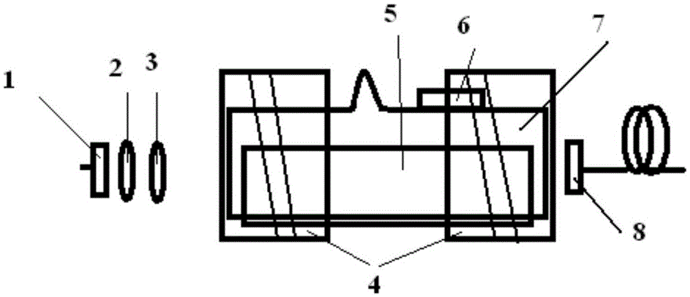
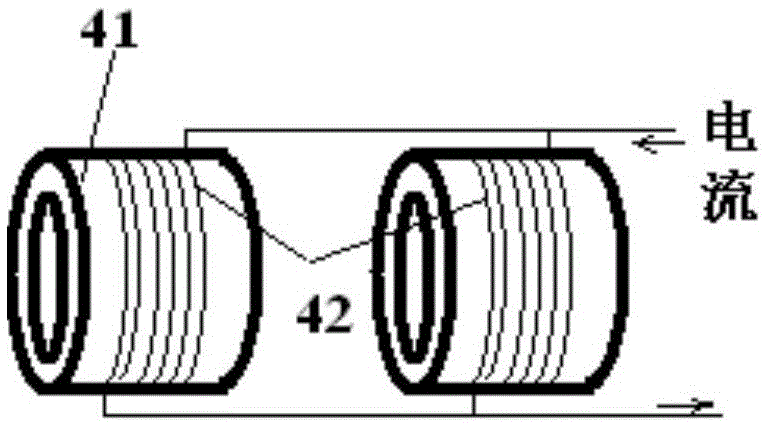
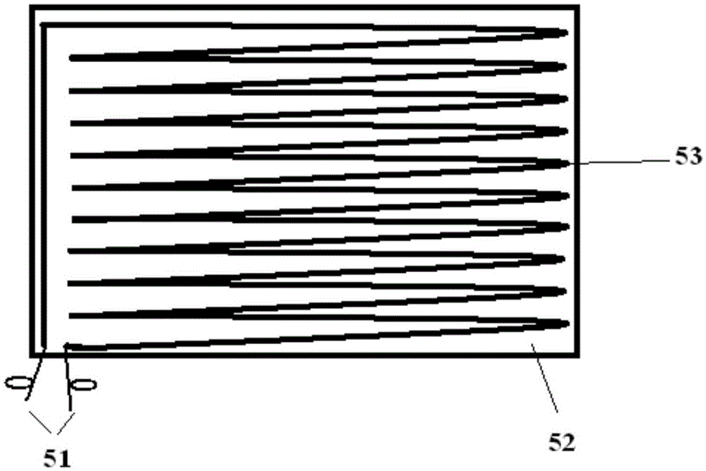
[0029] figure 1 It is a structural schematic diagram of a small-scale CPT atomic clock physical system that the present invention relates to; figure 2 is the structural diagram of the anti-Helmholtz coil; image 3 It is the structure diagram of the low-electromagnetic thin-film electric heating sheet. Only one of them is shown in the figure, and the layout of the other sheet is exactly the same as that of the surface, and the two sheets are completely bonded together with their backs facing each other.

[0030] Such as figure 1 As shown, the present invention provides a small CPT atomic clock physics system, which includes a laser part and an atomic gas chamber part. in:

[0031] The laser part includes a VCSEL laser tube 1, an aperture diaphragm 2 and a λ / 4 wave plate 3;

[0032] The atomic gas chamber part includes an atomic gas chamber 7, a C field coil 4, a ...


PUM


Abstract

The invention relates to a small CPT atomic clock physical system, and belongs to the technical field of atomic frequency standard. The physical system comprises a laser portion and an atom air chamber portion. The laser portion comprises a VCSEL laser tube, an aperture diaphragm, and a [lambda] / 4 wave plate. The atom air chamber portion comprises an atom air chamber, a C field coil, a thermistor, a low electromagnetic film electric heating sheet, and a photoelectric detector. The C field coil uses a reverse Helmholtz coil structure to realize. Heating methods of the low electromagnetic film electric heating sheet and high-frequency AC electric heating are used to heat the atom air chamber. The system uses a vacuum heat insulation technology to package. The output frequency of the physical system is high in stability, stable in performance, small in volume, low in power consumption, and low in cost, and is especially suitable to be used for a glass type atom air chamber whose sealing port is on the central position of a cylindrical surface.

Description

technical field [0001] The invention relates to a small CPT atomic clock physical system, which belongs to the technical field of small atomic frequency standards. Background technique [0002] Atomic clock, professional language is called atomic time frequency standard (abbreviated as atomic frequency standard, Atomic Frequency Standard). Since it came out in 1948, the research on atomic clock has made great progress in more than half a century. Traditional atomic clocks have already formed an industry and entered commercial production, and have been widely used. Especially in the field of satellite navigation and information, such as GPS, Beidou navigation, etc., the core control device is the atomic clock. Without an atomic clock, it is unimaginable to locate at a distance of tens of meters, a few meters or even a few centimeters. [0003] In 1976, Alzetta and others discovered the CPT phenomenon for the first time in the experiment of using two-frequency lasers to act ...

Claims


Application Information

Patent Timeline
Patent Type & Authority Applications(China)
IPC IPC(8): G04F5/14
CPCG04F5/14
Inventor 卢向东王巍王豪张笑楠王学锋
Owner BEIJING INST OF AEROSPACE CONTROL DEVICES
Why Eureka
Eureka Blog
Learn More