Cooling device for travelling-wave tube amplifier

A traveling wave tube amplifier and cooling device technology, applied in the cooling method of transit time type electron tubes, discharge tubes, transit time type electron tubes, etc., can solve problems such as drop, difficult internal temperature, influence on operation stability, etc.

Active Publication Date: 2016-04-06
SICHUAN JIUZHOU ELECTRIC GROUP
View PDF3 Cites 2 Cited by
  • Summary
  • Abstract
  • Description
  • Claims
  • Application Information

AI Technical Summary

Problems solved by technology

[0004] The air-cooled cooling method mainly has the following problems: First, the cooling speed is slow, which will cause the local temperature of the traveling wave tube amplifier to rise too fast in a short period of time, affecting its operation stability
Second, the heat taken away by cooling is small, and the temperature remains high during long-term operation, causing thermal damage to components
Third, the location of the TWT PFC (PowerFactorCorrector) power supply and the high-voltage power supply device are adjacent to each other. It is difficult to reduce the internal temperature of the air-cooled method, and the cooling effect is not good, which seriously affects the service life of the TWT amplifier.

Method used


Image

  • Cooling device for travelling-wave tube amplifier
  • Cooling device for travelling-wave tube amplifier
  • Cooling device for travelling-wave tube amplifier

Examples


Embodiment Construction

[0028] The present invention will be further described below in conjunction with accompanying drawing.

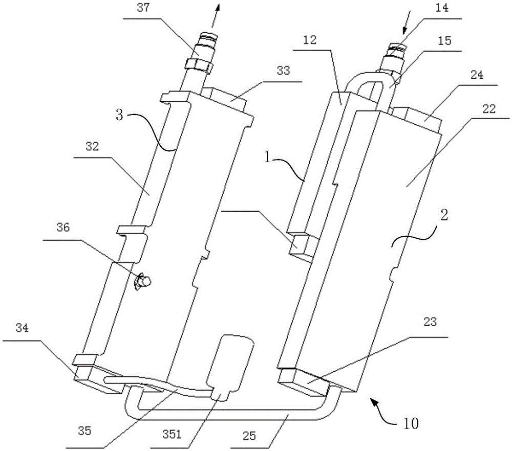
[0029] Such as figure 1 As shown, a cooling device 10 for a traveling wave tube amplifier includes a first cooling plate 1 , a second cooling plate 2 and a third cooling plate 3 . The first cooling plate 1, the second cooling plate 2, and the third cooling plate 3 are provided with flow channels, and the flow channels in the first cooling plate 1, the second cooling plate 2, and the third cooling plate 3 pass through external pipelines in sequence connected.

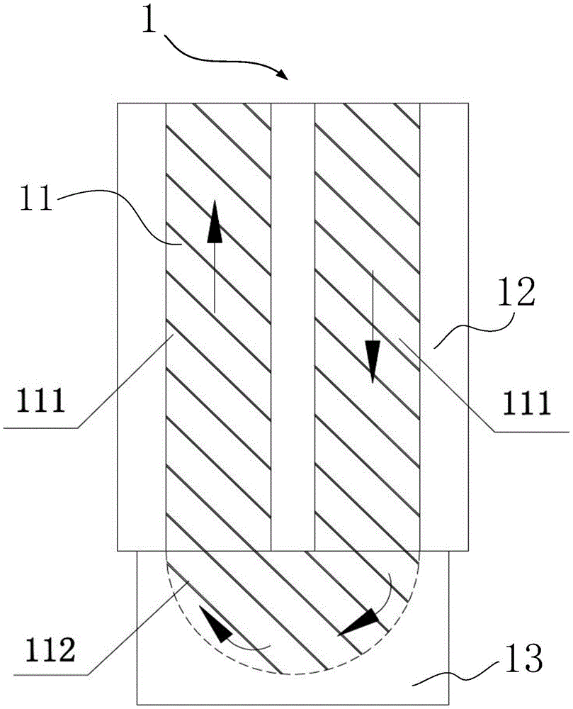
[0030] Such as figure 2 As shown, the first cooling plate 1 includes a first body 12 and a first deflector block 13 . The first body 12 is a roughly plate-shaped structure. The first deflector block 13 has a substantially straight hexahedron structure. The outer contour of the first deflector block is a roughly cubic structure. The first guide block 13 is disposed at one end of the first body 12 . The first co...


PUM


Abstract

The invention relates to a cooling device for a travelling-wave tube amplifier. The cooling device comprises a first cooling plate, a second cooling plate and a third cooling plate, wherein the first cooling plate, the second cooling plate and the third cooling plate are all internally provided with cooling liquid runners, the cooling liquid runners in the first cooling plate, the second cooling plate and the third cooling plate are sequentially communicated so that a cooling liquid can sequentially pass through the first cooling plate, the second cooling plate and the third cooling plate, and the first cooling plate, the second cooling plate and the third cooling plate are sequentially used for cooling a high-voltage power supply of the amplifier, a power factor corrector (PFC) power supply and a travelling-wave tube. By the cooling device, the problems that the travelling-wave tube amplifier is instable in running, a component is thermally damaged and the service lifetime of a system is reduced caused by slow cooling speed and low cooling rate in an air-cooling mode are solved.

Description

technical field [0001] The invention relates to a cooling technology, in particular to a cooling device for a traveling wave tube amplifier. Background technique [0002] The Ku-band traveling wave tube amplifier is a signal amplification device widely used in the field of radio and television satellite transmission. It is equipped with a microwave electron tube that continuously modulates the speed of the electron beam to realize the amplification function. Therefore, when the TWT amplifier is working, a large amount of heat will be generated. If the heat cannot be discharged in time, it will seriously affect the normal operation and service life of the TWT amplifier. [0003] The normal operating temperature of the traveling wave tube is generally below 55°C, and its shell temperature should also be below 85°C. The current cooling method of the Ku-band traveling wave tube amplifier is forced air cooling, and the cooling method of the traveling wave tube amplifier in the n...

Claims


Application Information

Patent Timeline
Patent Type & Authority Applications(China)
IPC IPC(8): H01J23/00
CPCH01J23/005
Inventor 汪梦苗东陈志王茂荣邓杰何华卫
Owner SICHUAN JIUZHOU ELECTRIC GROUP
Why Eureka
Try Eureka