Vehicle-mounted external illuminating radar antenna framework folding and unfolding mechanism

A technology of external radiation source radar and antenna skeleton, which is applied to antennas, antenna parts, antenna supports/installation devices, etc., can solve the problems of prolonging the deployment time of radar systems, time-consuming and laborious installation, and increasing installation time. Adjustment precision, smooth transmission, space saving effect

Active Publication Date: 2016-04-06
HARBIN INST OF TECH +1
View PDF6 Cites 6 Cited by
  • Summary
  • Abstract
  • Description
  • Claims
  • Application Information

AI Technical Summary

Problems solved by technology

However, separate transportation will cause the following problems: it will inevitably increase the installation time and greatly prolong the deployment time of the entire radar system; separate transportation will put forward higher requirements for the accuracy and reliability of the antenna skeleton deployment mechanism
[0004] The existing antenna framework deployment schemes are mostly manually installed and disassembled. Multiple load-bearing rods are installed and locked separately. Although this method has high reliability, it is time-consuming and laborious to install, and the deployment time is very long. Can no longer meet the needs of modern warfare

Method used


Image

  • Vehicle-mounted external illuminating radar antenna framework folding and unfolding mechanism
  • Vehicle-mounted external illuminating radar antenna framework folding and unfolding mechanism
  • Vehicle-mounted external illuminating radar antenna framework folding and unfolding mechanism

Examples


specific Embodiment approach 1

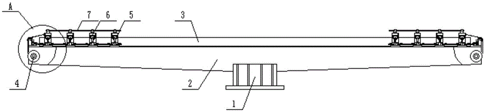
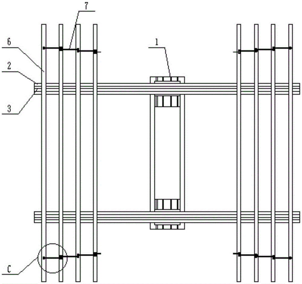
[0024] Combine below figure 1 , 2 , 3, 4, 5, 6, 7, and 8 illustrate this embodiment. The present invention relates to the field of military vehicle-mounted radar technology, more specifically, a vehicle-mounted external radiation source radar antenna skeleton folding mechanism, including a main support frame 1, Support arm 2, guiding device 3, driving device 4, locking mechanism 5, antenna bearing rod 6 and traction mechanism 7, adapt to a wide range of antenna diameters, and there is no limit to the length and number of antenna bearing rods; the driving mechanism adopts motor deceleration The transmission mechanism used in conjunction with the wire rope and the guide wheel has stable transmission, adjustable speed, and low cost; the traction mechanism realizes the motion transmission between the antenna load-bearing rods, so that the drive mechanism only needs to be arranged on one load-bearing rod, which simplifies The driving mechanism also saves space; when the traction m...

specific Embodiment approach 2

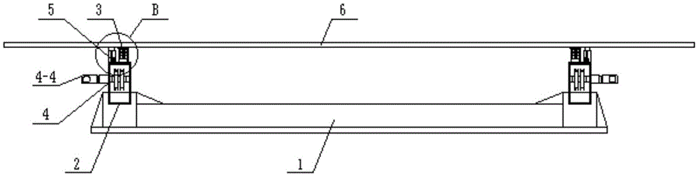
[0027] Combine below figure 1 , 2 , 3, 4, 5, 6, 7, and 8 illustrate this embodiment, and this embodiment will further describe Embodiment 1. The guide device 3 includes a guide wheel bracket 3-1, a guide wheel 3-2, and a circular guide rail 3 -3 and the guide wheel groove 3-4, the guide wheel groove 3-4 is fixedly connected with the support arm 2, here fixedly connected by screws, for detachable connection, convenient to replace parts. The circular guide rail 3-3 is fixedly connected with the guide wheel groove 3-4, and is connected by welding here, and has an integrated structure. The guide wheel support 3-1 is fixedly connected with the antenna load-bearing rod 6, here fixedly connected by screws, which is a detachable connection for easy replacement of parts. The guide wheel 3-2 is movably connected with the guide wheel support 3-1, and the guide wheel 3-2 is symmetrically arranged at the two ends of the guide wheel support 3-1, the guide wheel 3-2 is movably connected wi...

specific Embodiment approach 3

[0028] Combine below figure 1 , 2 , 3, 4, 5, 6, 7, and 8 illustrate this embodiment, and this embodiment will further describe Embodiment 1. The drive device 4 includes a drive pulley 4-1, a fixed pulley 4-2, and a wire rope 4-3 and the motor reducer 4-4, the drive pulley 4-1 is arranged in the support arm 2, the motor reducer 4-4 is connected with the drive pulley 4-1, and the motor reducer 4-4 is concentric with the drive pulley 4-1 The fixed pulley 4-2 is set on the upper end of the support arm 2 and is located above the driving pulley 4-1. One end of the wire rope 4-3 is connected to the driving pulley 4-1, and the other end of the wire rope 4-3 is connected to the antenna bearing. Power bar 6 is connected, and contacts with fixed pulley 4-2. The motor reducer 4-4 drives the driving pulley 4-1 to rotate, and the driving pulley 4-1 shrinks the wire rope 4-3 so as to drive the antenna bearing rod 6 to move in the horizontal direction.


PUM


Abstract

The invention relates to the technical field of vehicle-mounted military radars, in particular to a vehicle-mounted external illuminating radar antenna framework folding and unfolding mechanism. The adapted size range of the antenna aperture is relatively wide and antenna bearing rods are not limited in length and number; a traction mechanism realizes motion transmission among the antenna bearing rods, so that a driving mechanism only needs to be arranged on one bearing rod and the space is saved while the driving mechanism is simplified; a locking mechanism is simple to operate, and the bearing rods can be locked by one-step operation, so that large amounts of time and manpower costs are saved; in the locking mechanism, a taper pin is in conical fit with a taper pin seat, so that compared with a cylindrical surface, the situation of jamming caused by coaxiality can be avoided; a supporting arm is mounted on a main supporting frame; a driving apparatus is arranged on the edge of the supporting arm and connected with the antenna bearing rods; the traction mechanism is connected with the antenna bearing rods; and a guide apparatus and the locking mechanism are located between the supporting arm and the antenna bearing rods.

Description

technical field [0001] The invention relates to the technical field of military vehicle-mounted radar, and more specifically relates to a vehicle-mounted external radiation source radar antenna skeleton folding mechanism. Background technique [0002] High mobility is one of the key technical indicators of ground vehicle radars. In recent years, high mobility radars are mainly based on radars with small-caliber antennas. With the needs of information warfare and the development of radar detection technology, in order to detect incoming targets in advance and improve the detection distance, large-scale planar array antennas have been widely used in ground medium and long-range three-coordinate military radars. Due to the limitations of carrying capacity and transportation conditions, large planar antennas must be processed in blocks to meet cross-country transportation requirements. Therefore, in the process of radar erection, it is necessary to carry out links such as anten...

Claims


Application Information

Patent Timeline
Patent Type & Authority Applications(China)
IPC IPC(8): H01Q1/12H01Q1/18H01Q1/32
CPCH01Q1/1235H01Q1/18H01Q1/32
Inventor 彭高亮孙瑜薛渊
Owner HARBIN INST OF TECH
Why Eureka
Try Eureka