Lightweight dielectric-filled multi-beam cylindrical Luneberg lens antenna

A technology of dielectric filling and Lumber lens, which is applied in the direction of antennas and electrical components, can solve the problems of unfavorable weight, low antenna aperture efficiency, and poor anisotropy performance of lens antennas, etc., to reduce the overall height and reduce divergence Effect

Inactive Publication Date: 2016-04-06
UNIV OF ELECTRONICS SCI & TECH OF CHINA
View PDF3 Cites 50 Cited by
  • Summary
  • Abstract
  • Description
  • Claims
  • Application Information

AI Technical Summary

Problems solved by technology

[0005] The paper entitled "Aslicedspherical Luneburglens" published by S. Rondineau et al. on IEEEAntennasWirelessPropag. (vol.2, pp.163-166, 2003) introduces a thin-sheet Luneburglens antenna, which is drilled on Teflon Holes with different densities and sizes, and then glue and assemble the drilled multi-layer circular polytetrafluoroethylene sheets to design Lunberg lens antennas. The lens antennas designed b

Method used


Image

  • Lightweight dielectric-filled multi-beam cylindrical Luneberg lens antenna
  • Lightweight dielectric-filled multi-beam cylindrical Luneberg lens antenna
  • Lightweight dielectric-filled multi-beam cylindrical Luneberg lens antenna

Examples


Embodiment Construction

[0024] In order to make the purpose, technical solution and advantages of the present invention clearer, the present invention will be further described in detail below in conjunction with the implementation methods and accompanying drawings.

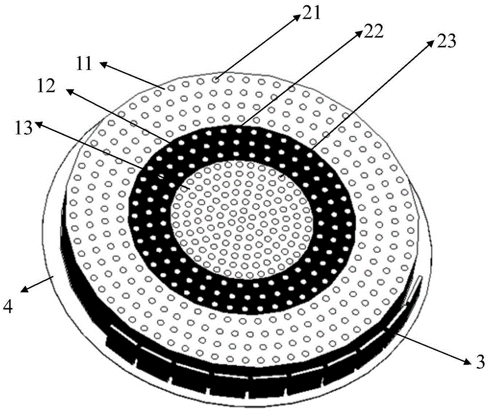
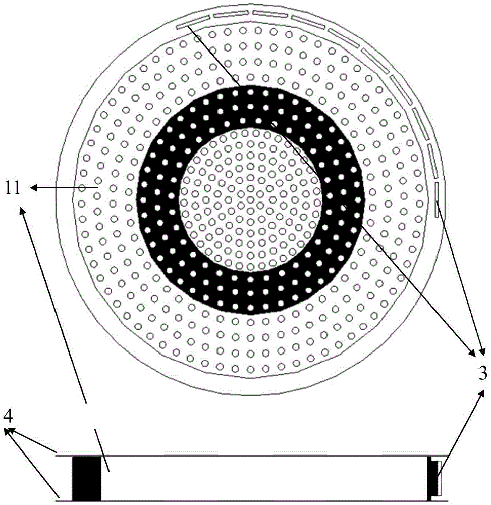
[0025] figure 1 and figure 2 The structural diagram of a lightweight dielectric-filled multi-beam cylindrical Lunberg lens antenna is described in detail. According to the illustration, the device mainly includes a cylindrical Lunberg lens antenna, an arc array 3 composed of 10 E-type microstrip patch feed sources, and two parallel metal plates 4, in which the cylindrical Lunberg lens consists of three layers : Outer layer lens 11, middle layer lens 12, inner layer lens 13, three-layer lens all adopts low dielectric constant lightweight substrate material, adopts lightweight foam as substrate material in the present embodiment, perforates and fills on substrate material High dielectric constant material, forming a dielectric rod. In...


PUM


Abstract

The invention discloses a lightweight dielectric-filled multi-beam cylindrical Luneberg lens antenna applied to multi-beam directional communication and beam scanning. The basic structure of the lightweight dielectric-filled multi-beam cylindrical Luneberg lens antenna comprises a cylindrical Luneberg dielectric lens and a curved array (3), wherein the curved array (3) comprises a plurality of E-shaped microstrip antenna feed sources; the cylindrical Luneberg dielectric lens between two parallel metal plates (4) is divided into three layers, namely an outer layer lens (11), a middle layer lens (12) and an inner layer lens (13); the three layers all adopt lightweight foam with a low dielectric constant as a substrate material; holes are formed in the substrate material and are filled with dielectric rods with high dielectric constants; the holes in the three lenses sequentially become dense from the outside to the inside; and the curved array (3) is fixed between the two parallel metal plates (4). The holes are formed in the substrate material with the low dielectric constant and are filled with a dielectric material with a high dielectric constant, so that required gradient dielectric constant is achieved; and lightweight of the antenna is achieved when the electrical property of the antenna is met.

Description

technical field [0001] The invention relates to a Luneberg lens antenna belonging to the technical field of antenna engineering, in particular to a medium-filled cylindrical Luneberg lens antenna suitable for multi-beam directional communication and beam scanning. Background technique [0002] With the increasing demand for multi-beam antennas in technical fields such as satellite communications, radar systems, and electronic countermeasures, the requirements for multi-beam antennas are also increasing accordingly. In addition to the requirements such as wide beam coverage, it is also necessary to take into account the needs of scanning speed, cost, and environment. [0003] Most of the traditional crafts use dielectric plastic foam heat foaming method to realize the production of Lumber lens antenna. For example, in the patent CN101057370, the foamed plastic beads are foamed by the mold opening method, but the process flow of this method is very complicated and the foaming ...

Claims


Application Information

Patent Timeline
IPC IPC(8): H01Q19/06H01Q15/02
CPCH01Q19/06H01Q15/02
Inventor 杨仕文蒋秋芳陈益凯吴坚林张航宇
Owner UNIV OF ELECTRONICS SCI & TECH OF CHINA
Why Eureka
Try Eureka