Vortex self-cleaning oil well pump

A self-cleaning, oil well pump technology, applied to pumps, parts of pumping devices for elastic fluids, pump components, etc., can solve the problems of fixed valve clogging and sealing, short pump inspection period, fixed valve full of falling objects, etc. , to prevent blockage of the pump valve, increase fullness, and speed up the effect

Inactive Publication Date: 2016-04-13
XI'AN PETROLEUM UNIVERSITY
View PDF7 Cites 2 Cited by
  • Summary
  • Abstract
  • Description
  • Claims
  • Application Information

AI Technical Summary

Problems solved by technology

[0002] In recent years, domestic oil fields have successively entered the late stage of production. Due to the influence of pipe rod corrosion debris and viscous suspended impurities such as sand consolidation agents after downhole chemical sand control operations, problems such as pump sticking and leakage have become more prominent. The main problems are as follows: : 1) Rust flakes, scale flakes, and suspended impurities such as downhole mud sand, filling resin, gel, etc. produced in the oil casing annulus, after being sucked into the oil well pump, deposit near the fixed valve, causing the fixed valve to be blocked or not tightly sealed; 2) During the operation of the lower pump, iron filings and scale flakes generated by the pole scraping the inner wall of the oil pipe fell into the pump chamber, causing the fixed valve to be full of debris before the oil well pump started, directly affecting the opening and closing of the fixed valve
The above problems lead to short pump inspection cycle, high maintenance cost, and affect production efficiency
For the viscous impurities suspended in the downhole, conventional oil well pumps cannot discharge them in time, and most of the sand control pumps used are mainly sand-setting structures, and the sand storage space is limited, so the treatment effect on such impurities is not ideal

Method used


Image

  • Vortex self-cleaning oil well pump
  • Vortex self-cleaning oil well pump
  • Vortex self-cleaning oil well pump

Examples


Embodiment Construction

[0020] The present invention will be described in further detail below in conjunction with the accompanying drawings.

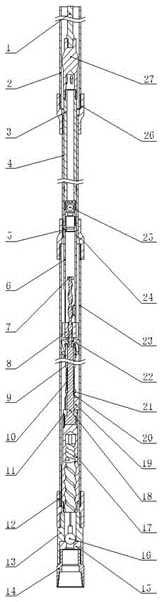
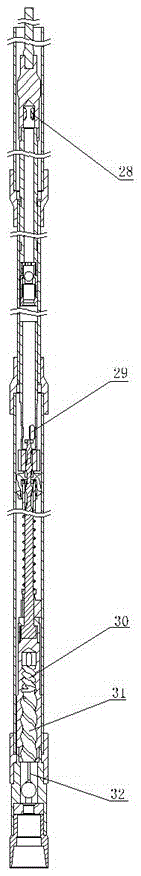
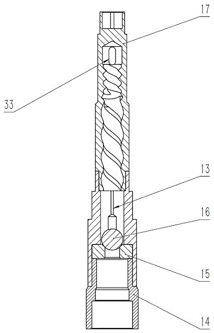
[0021] Referring to Figures 1, 2 and 3, a vortex self-cleaning oil well pump includes a plunger assembly, a pump barrel assembly, a vortex spinner and a swirl fixed valve assembly; the plunger assembly includes a plunger 3, The upper end of the plunger is connected to the traveling valve cover 27, and the lower end is connected to the downstream traveling valve assembly 25; the lower end of the downstream traveling valve assembly 25 is threadedly connected to the lower pressure seat 5, and the lower pressure seat 5 squeezes the transition cylinder 6; the plunger assembly is located in the pump Inside the barrel assembly, the pump barrel assembly includes the oil pipe 2, the oil pipe 2 is connected to the oil pipe collar 26, the lower end of the oil pipe collar is connected to the pump barrel 4 and the pump barrel collar 24; the lower end of the pump barrel col...


PUM


Abstract

The invention discloses a vortex self-cleaning oil well pump which comprises a plunger assembly, a pump cylinder assembly, a vortex rotary lifting device and a rotational flow fixing valve assembly. The vortex rotary lifting device comprises a rotor, a stator, a compression spring, a guiding cylinder, an upper straightening block and a lower straightening block. The rotational flow fixing valve assembly comprises a rotational flow guiding cylinder, a fixing valve cover, a fixing valve and a fixing valve seat. The pump cylinder assembly comprises a pump cylinder and a pump cylinder coupling. The pump cylinder coupling is connected with a lengthened short joint. The vortex rotary lifting device is arranged in the lengthened short joint. The stator is connected with the rotational flow guiding cylinder through a stator connector. The lower straightening block is arranged on the stator in a sleeving manner and is located through a locking nut. The upper end of the locking nut is sleeved with a spring seat and the compression spring. The upper end of the guiding cylinder is sequentially connected with the rotor, the upper straightening block and a stop nut. The rotational flow fixing valve assembly is arranged at the lower end of the lengthened short joint and is connected with the lower end of the coupling through the upper end of the fixing valve cover. Vortex is generated in a pump cavity, impurities which are sucked in are carried out of the oil well pump, the pump cavity is cleaned, impurities are prevented from being deposited in the fixing valve, the overhaul period is prolonged, and production efficiency is improved.

Description

technical field [0001] The invention belongs to the technical field of oil well pumps in oil fields, in particular to a vortex self-cleaning oil well pump. Background technique [0002] In recent years, domestic oil fields have successively entered the late stage of production. Due to the influence of pipe rod corrosion debris and viscous suspended impurities such as sand consolidation agents after downhole chemical sand control operations, problems such as pump sticking and leakage have become more and more prominent. The main problems are as follows: : 1) Rust flakes, scale flakes, and suspended impurities such as downhole mud sand, filling resin, gel, etc. produced in the oil casing annulus, after being sucked into the oil well pump, deposit near the fixed valve, causing the fixed valve to be blocked or not tightly sealed; 2) During the pump down operation, the iron filings and scale flakes generated by the rod column scraping the inner wall of the tubing fell into the pu...

Claims


Application Information

Patent Timeline
Patent Type & Authority Applications(China)
IPC IPC(8): F04B53/00F04B53/10F04B47/00
CPCF04B47/00F04B53/00F04B53/10
Inventor 屈文涛郭怡潇苟建升孙旭光袁比飞
Owner XI'AN PETROLEUM UNIVERSITY
Why Eureka
Try Eureka