
Grain drying device

A technology of grain drying and drying tower, applied in grain drying, heating device, preservation of seeds by drying, etc., can solve the problems of increasing resource consumption and destroying the drying environment, and achieve the effect of improving efficiency, reducing volume and simple structure

Active Publication Date: 2016-04-13
苏州市农业机械有限公司
View PDF5 Cites 7 Cited by
  • Summary
  • Abstract
  • Description
  • Claims
  • Application Information

AI Technical Summary

Problems solved by technology

[0004] Therefore, the existing heat pump grain dryer needs to be equipped with a defrosting device. One method is to use a four-way valve to make the flow direction of the refrigerant in the condenser and evaporator opposite to the normal process state of the dryer, that is, through high temperature and high pressure refrigeration. The agent flows into the evaporator to achieve the defrosting effect, but due to the conversion of the heat exchange effect between the condenser and the evaporator, the condenser that originally supplied the dry hot air in the barn is converted to provide cold air, and this process will cause the cold air to flow back into the barn , to destroy the original dry environment in the barn; another method is to install a resistance wire on the evaporator, connect the resistance wire to the controller, and defrost the evaporator through the resistance wire. A dry environment inside the desiccator, but with increased resource consumption

Method used


Image

  • Grain drying device

Examples


Embodiment Construction

[0029] The above solution will be further described below in conjunction with specific embodiments. It should be understood that these examples are used to illustrate the present invention and not to limit the scope of the present invention. The implementation conditions used in the examples can be further adjusted according to the conditions of specific manufacturers, and the implementation conditions not indicated are usually the conditions in routine experiments.

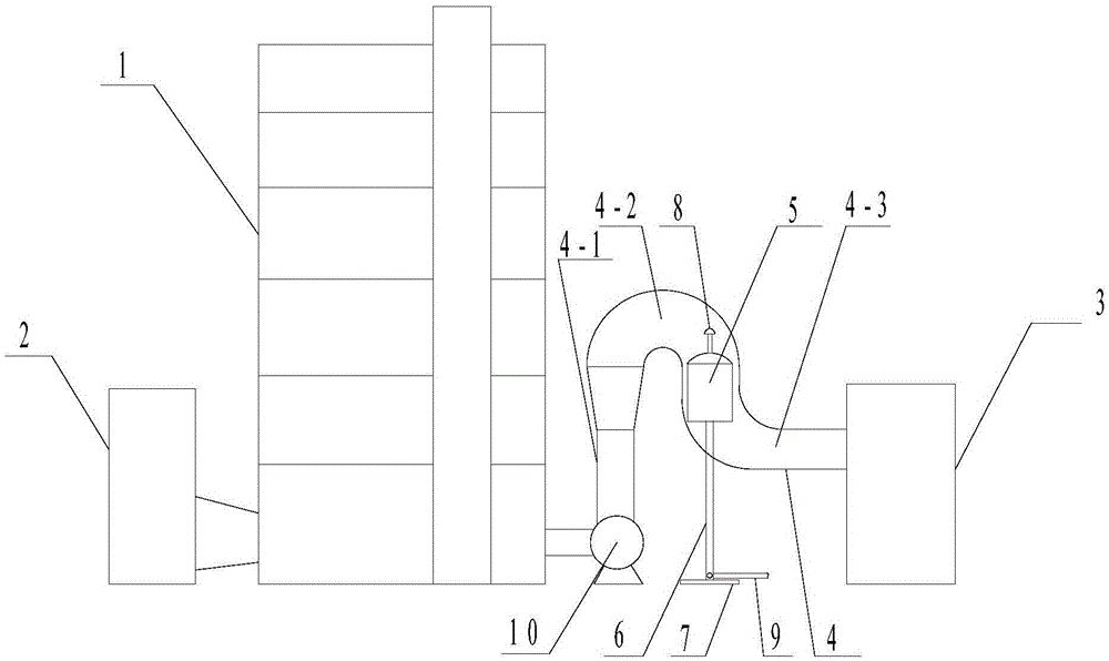
[0030] see figure 1 , is a structural schematic diagram of an embodiment of the present invention, providing a grain drying device, which includes a drying tower 1, one side of the drying tower 1 is communicated with a heat pump 2 for providing hot air, and the other side of the drying tower 1 is provided with a A dust collection chamber 3 for collecting grain dust, the dust collection chamber 3 communicates with the drying tower 2 through a dust discharge pipe 4, and a blower 10 is provided between the inlet en...


PUM


Abstract

The invention discloses a grain drying device. The grain drying device comprises a drying tower (1); one side of the drying tower (1) is communicated with a heat pump (2) for supplying hot wind; a dust collecting chamber (3) for collecting grain dust is arranged on the other side of the drying tower (1), and is communicated with the drying tower (1) through a dust removing pipe (4); and an evaporator (5) of the heat pump (2) is arranged in the dust removing pipe (4). The grain drying device is provided with the evaporator of the heat pump in the dust removing pipe, can improve the efficiency of the evaporator by using heat of dust-contained gas, and is energy-saved and environment-friendly.

Description

technical field [0001] The invention relates to the technical field of drying equipment, in particular to a grain drying device. Background technique [0002] The process of grain from harvesting to storage requires drying of the grain to facilitate subsequent processing or long-term storage of the grain. The heat pump grain dryer has the advantages of less pollution, low energy consumption and low cost compared with the traditional dryer by burning fuel. Therefore, there are more and more heat pump grain dryers in the prior art. Dryers used to replace traditional fuel-burning methods. [0003] The grain dryer in the prior art mainly includes a heat pump and a drying tower. The heat pump compresses the gaseous refrigerant into a high-temperature and high-pressure gaseous refrigerant through a compressor, and then sends it to the condenser to dissipate heat to become a liquid refrigerant at room temperature and high pressure. During this process, the heat emitted by the con...

Claims


Application Information

Patent Timeline
Patent Type & Authority Applications(China)
IPC IPC(8): F26B23/00A23B9/08
CPCA23B9/08F26B23/005F26B2200/06Y02A40/90Y02P60/85
Inventor 陶亚平
Owner 苏州市农业机械有限公司
Learn More