Laser photography measuring system and camera calibration method

A photogrammetry and laser rangefinder technology, which is applied to measurement devices, camera devices, instruments, etc., can solve the problems of increasing calibration error, decreasing measurement accuracy, and increasing calibration workload.

Active Publication Date: 2016-04-13
SHANDONG UNIV OF SCI & TECH
View PDF13 Cites 19 Cited by
  • Summary
  • Abstract
  • Description
  • Claims
  • Application Information

AI Technical Summary

Problems solved by technology

[0006] In addition, for large-scale measured objects, multiple cameras are often used for simultaneous measurement during actual measurement, and there is no relative positional relationship between multiple cameras, so each camera needs to be calibrated separately, which increases the calibration workload. At the same time, it will increase the calibration error, resulting in a decrease in measurement accuracy.

Method used


Image

  • Laser photography measuring system and camera calibration method
  • Laser photography measuring system and camera calibration method
  • Laser photography measuring system and camera calibration method

Examples


Embodiment 1

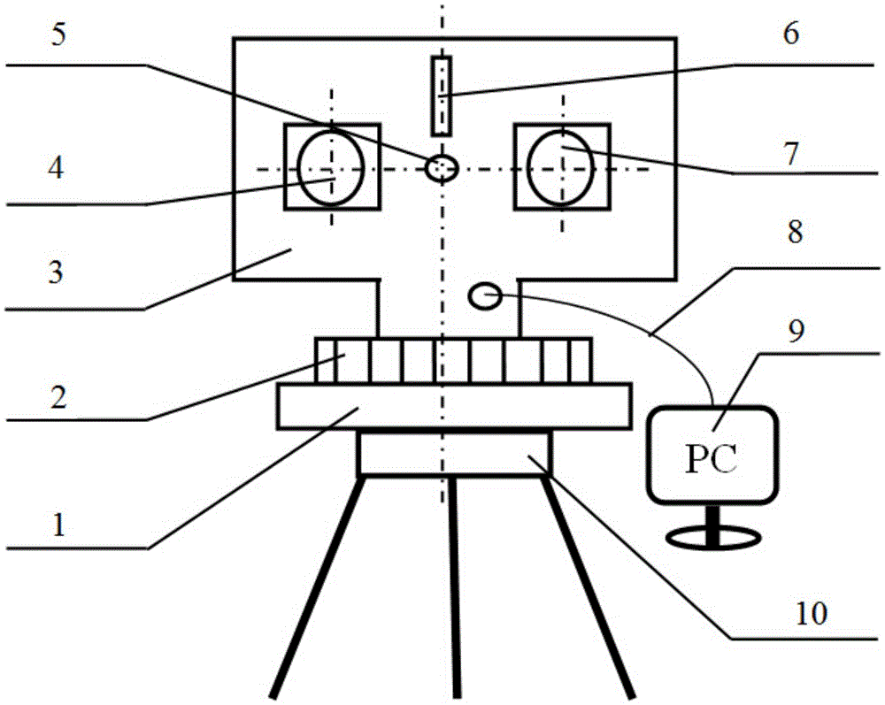
[0044] Such as figure 1 with figure 2 As shown, a laser photogrammetry system includes a measuring device and a calibration device, wherein the measuring device includes a base 1, a horizontal index plate 2, a bracket 3, two cameras 4 and 7, and a line laser transmitter 6. Laser range finder 5, data line 8, computer 9. Wherein, the camera 4 and the camera 7 are symmetrically installed on both sides of the laser range finder 5, and all three are installed on the bracket 3, and the computer 9 is connected with the control equipment in the bracket 3 through the data line 8. The measurement system also includes a tripod 10 , and the base 1 is connected and fixed to the tripod 10 through a threaded locking member on the tripod 10 .

[0045] Camera 4, camera 7, line laser emitter 6 and laser rangefinder 5 are all transmitted by computer 9 through data line 8 to transmit control commands, and the image data obtained are transmitted to computer 9 to facilitate data storage, calcula...

Embodiment 2

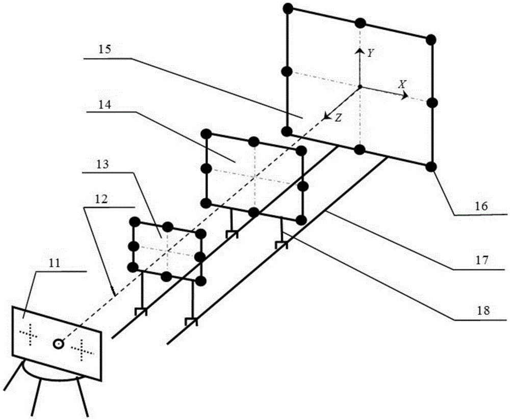
[0055] On the basis of Embodiment 1, this embodiment describes in detail the process of the camera calibration method using the laser photogrammetry system described in Embodiment 1.

[0056] This embodiment provides a camera calibration method for a laser photogrammetry system. First, obtain the coordinates of each object-space identification point 16 in the object-space coordinate system, and then adjust the measuring device 11 so that the two cameras are facing the object-space model to take pictures. Image data of 24 object space identification points 16. The image coordinates of each object space identification point 16 are read out by the execution program of the camera calibration method on the computer 9, and the two cameras and the laser are calculated by the execution program using the correspondence between the object space coordinates of the object space identification point 16 and the image coordinates. The pose coordinates and internal orientation element paramet...


PUM


Abstract

The invention relates to a laser photography measuring system and a camera calibration method. The system comprises a measuring device and a calibration device. The measuring device comprises a base, a support and a computer. The support is rotationally arranged on the base, the support is provided with cameras, a laser distance measuring device and a linear laser emitter, the laser distance measuring device and the linear laser emitter are located on the same vertical line, the two cameras are symmetrically arranged on the two sides of the laser distance measuring device, and the computer is electrically connected with the cameras, the laser distance measuring device and the linear laser emitter. The calibration device comprises three object space plates and evenly-distributed object space identification points. By means of the measuring device, the calibration device, the object space plates and the object space identification points, precise calibration of the cameras of the measuring system can be effectively achieved through photographing of the cameras and corresponding subsequent programmed programs. The camera calibration method is simple in step and easy to operate, and reliable bases are provided for subsequent laser photography measuring.

Description

technical field [0001] The invention relates to a laser photogrammetry system and a camera calibration method, belonging to the technical field of measurement device calibration methods. Background technique [0002] With the development of computer technology, photogrammetry and 3D reconstruction technology have been widely used in the fields of robot vision, industrial manufacturing, engineering construction, cultural relic protection and medical image analysis. Compared with using contact measuring instruments such as three-coordinate measuring instruments to measure the outer surface of objects, non-contact measurements such as laser scanning use non-contact photoelectric methods to quickly measure the three-dimensional shape of curved surfaces. With the advantages of high precision and wide application, it has certain application prospects in industrial engineering and other fields. In the measurement process, based on the image acquired by the visual sensor (such as a...

Claims


Application Information

Patent Timeline
Patent Type & Authority Applications(China)
IPC IPC(8): G01C11/02G01C25/00
CPCG01C11/02G01C25/00
Inventor 李学艺吕永刚曾庆良张鑫钟佩思王宁宁赵丹丹张庆雪
Owner SHANDONG UNIV OF SCI & TECH
Why Eureka
Try Eureka