Method and device for determining the leakage inductance of a doubly-fed induction generator

A doubly-fed induction and leakage inductance technology, applied in the field of leakage inductance, can solve problems such as poor control performance of doubly-fed induction generators, and achieve the effect of easy cost-effectiveness and improved response time

Active Publication Date: 2018-07-27
ABB (SCHWEIZ) AG
View PDF5 Cites 0 Cited by
  • Summary
  • Abstract
  • Description
  • Claims
  • Application Information

AI Technical Summary

Problems solved by technology

If these leakage inductance values ​​do not exactly match the real values ​​for some reason, these incorrect values ​​can cause poor control performance of the DFIG

Method used


Image

  • Method and device for determining the leakage inductance of a doubly-fed induction generator
  • Method and device for determining the leakage inductance of a doubly-fed induction generator
  • Method and device for determining the leakage inductance of a doubly-fed induction generator

Examples


Embodiment Construction

[0013] The application of the embodiments herein is not limited to any particular doubly-fed induction generator (DFIG) system, but it can be applied to various DFIG systems. Furthermore, the practice of the invention is not limited to, for example, any particular fundamental frequency or any particular voltage level.

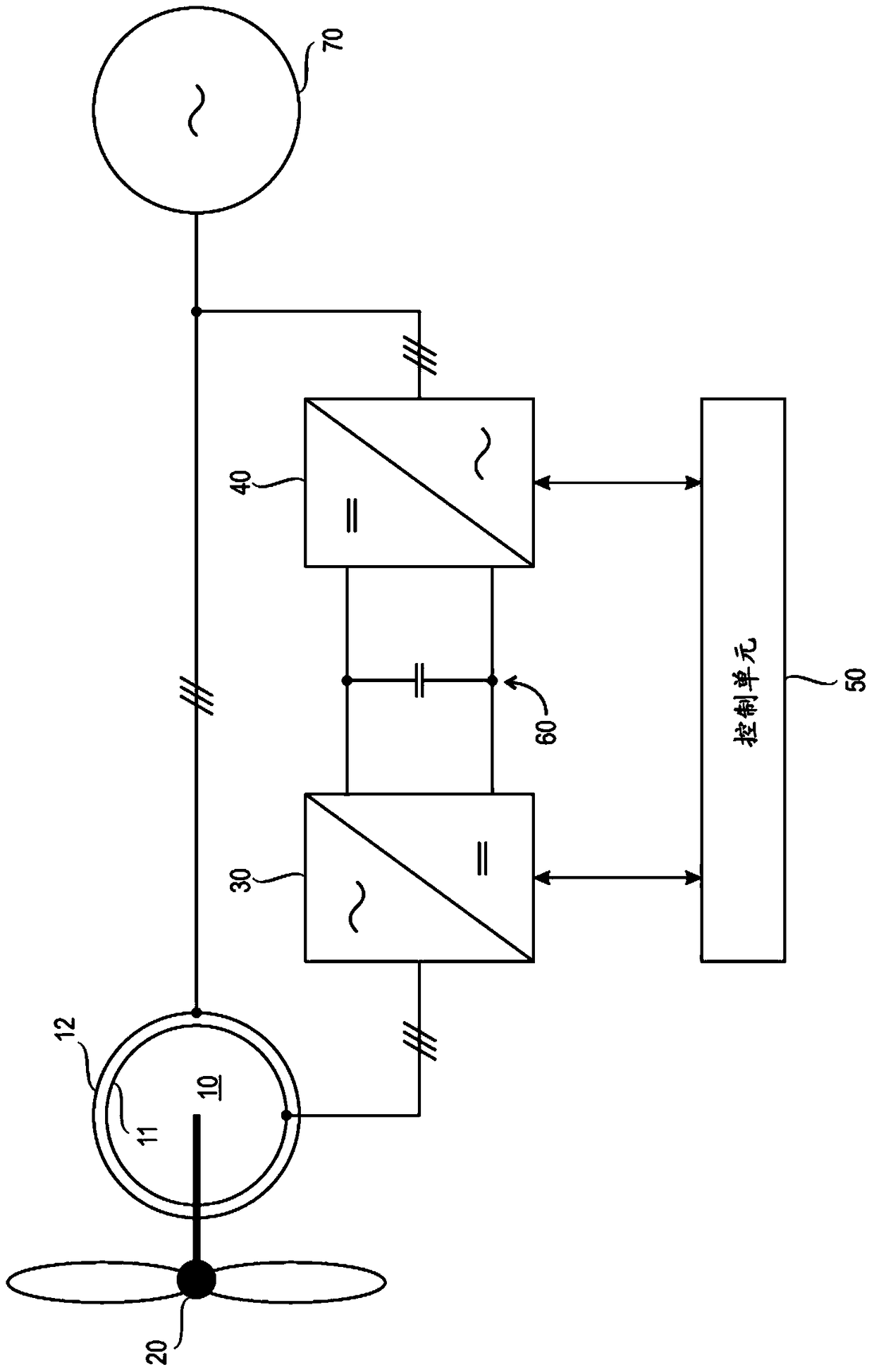
[0014] figure 1 A simplified block diagram of a doubly-fed induction generator system according to an embodiment is shown. The figure shows only the components necessary for understanding the invention. An exemplary doubly-fed induction generator system includes a doubly-fed induction generator 10 having a rotor 11 and a stator 12 . In this example, DFIG 10 is a three-phase DFIG. The rotor 11 of the DFIG 10 may be mechanically connected to a turbine 20 , such as a wind turbine, for driving the generator 10 . The stator 12 of the DFIG 10 may be electrically connected to a three-phase alternating current (AC) network 70 for providing the AC network 70 with el...


PUM


Abstract

A method and device for determining the leakage inductance of a doubly-fed induction generator DFIG (10), and an inverter and a frequency converter including the same. The method includes determining a stator voltage value, a rotor voltage value, and a rotor current value of the DFIG in response to the stator current of the DFIG being equal to or less than a first predetermined threshold, and calculating a rotor leakage inductance of the DFIG based on the determined values; and, In response to the rotor current of the DFIG being equal to or less than a second predetermined threshold, a stator voltage value, a rotor voltage value, and a stator current value of the DFIG are determined, and a stator leakage inductance of the DFIG is calculated based on the determined values.

Description

technical field [0001] The present invention relates to determining the leakage inductance of a doubly-fed induction generator. Background technique [0002] A wound rotor induction motor is a rotating electrical machine in which the rotor comprises windings. One example of such an electric machine is a doubly-fed induction machine commonly used as a generator - a doubly-fed induction generator (DFIG). Doubly-fed induction generators can be used as figure 1 In the configuration shown in the example, where, figure 1 The configuration shown in the example includes converters such that one converter (inverter 30) is electrically connected between the DC voltage intermediate circuit 60 and the rotor 11, while the other converter (rectifier 40) is electrically connected between the DC Between the voltage intermediate circuit 60 and the AC network 70 ; typically, the AC network 70 is powered by the generator 10 and is connected to the generator's stator 12 . For example, such ...

Claims


Application Information

Patent Timeline
Patent Type & Authority Patents(China)
IPC IPC(8): H02P9/00
CPCH02P9/007G01R31/343H02P23/0031
Inventor 托马斯·梅林雷约·卡莱维·弗塔嫩
Owner ABB (SCHWEIZ) AG
Why Eureka
Try Eureka