

Automatic juicer
A juicer and automatic technology, which is applied in household machinery for filtering food, household appliances, applications, etc., can solve the problems of smashing the peel into the pulp, shortening the life of the motor, and igniting the motor, so as to improve the taste and reduce the working noise Effect
- Summary
- Abstract
- Description
- Claims
- Application Information
AI Technical Summary
Problems solved by technology
Method used
Image

Examples
Embodiment 1
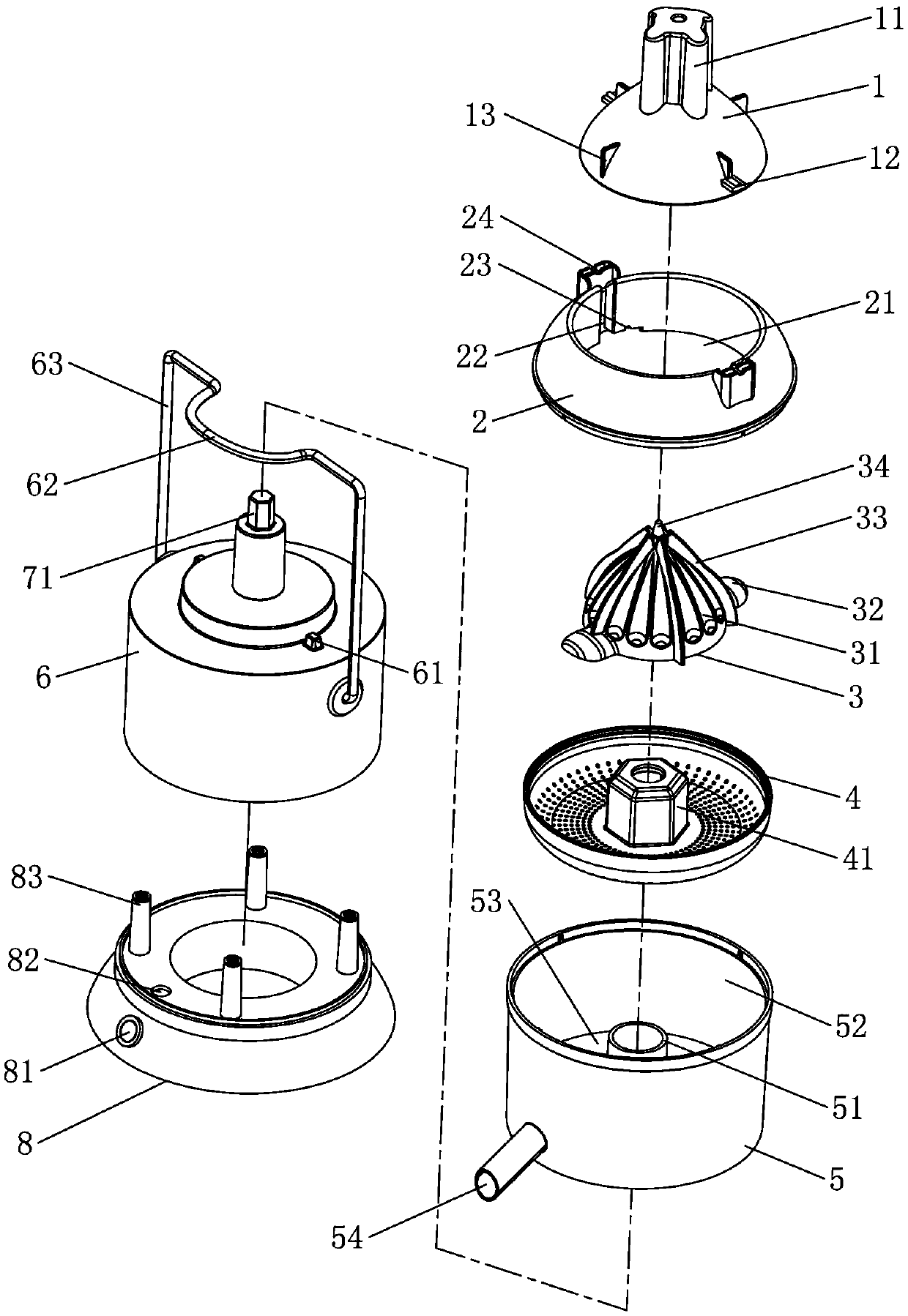
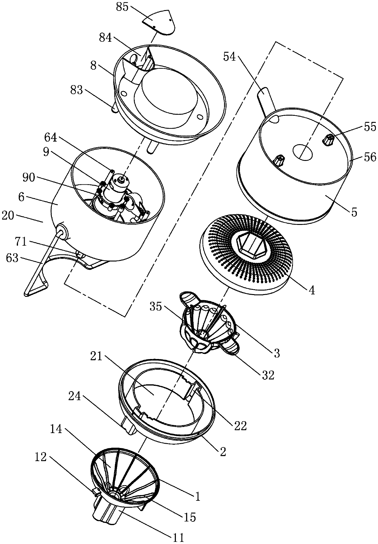
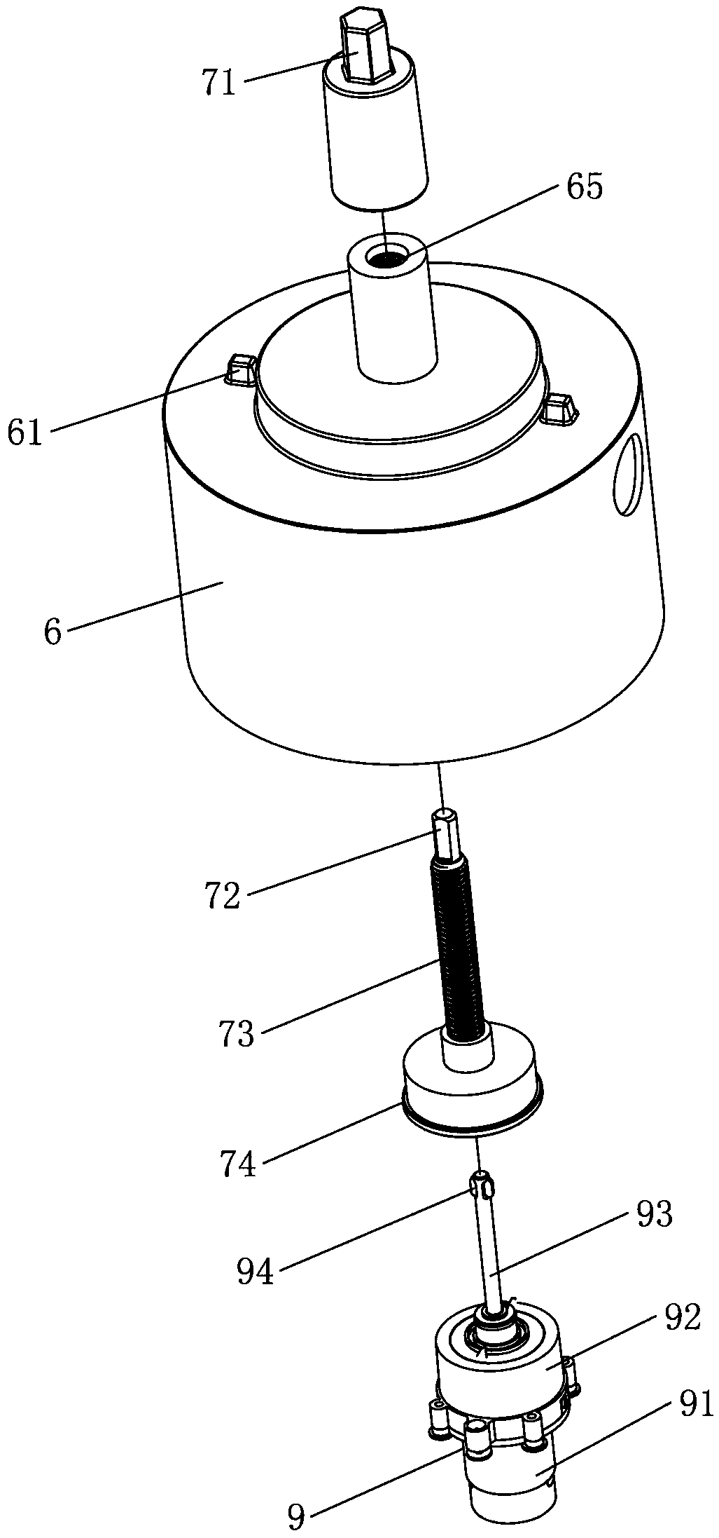
[0036] Embodiment one, see Figure 1 to Figure 4 As shown, an automatic juice extractor includes a machine head, a juice receiving cup 5, an upper juice extracting head 1 and a lower juice extracting head 3, the juice receiving cup 5 is arranged on the machine head, and the upper juice extracting head 1 is arranged on the juice receiving The upper and lower juice extraction heads 3 of the cup 5 are movable up and down in the juice receiving cup 5, and are located directly below the upper juice extraction head 1. The machine head includes a casing 6, a reduction motor 9 and a screw 73, and the reduction motor 9 is fixedly arranged In the casing 6, the output shaft 93 of the geared motor 9 is connected to the screw 73 in transmission, and they are axially slidably matched with each other. .
[0037] to combine Figure 5 to Figure 8 As shown, the geared motor 9 is fixed with a bracket 90 outside, and is fixedly connected with the casing 6 through the bracket 90 . Described red...
Embodiment 2
[0047] Embodiment two, the difference with embodiment one is: see Figure 9 and Figure 10 As shown, the geared motor 9 is linearly slid up and down and arranged in the casing 6 . Specifically: the casing 6 is vertically provided with two guide rods 60, the geared motor 9 slides with the guide rods 60 through the bracket 90, and the casing 6 is also provided with upper and lower limit switches corresponding to the movable path of the bracket 90. 40 and the lower limit switch 50, touch the upper limit switch 40 or the lower limit switch 50 in the process of the support 90 sliding up and down.
[0048] Its working principle is: taking extracting orange juice as an example, turn down the pull bar 63, remove the upper juice extracting head 1, put the half-cut orange pulp downward, and place it on the lower juice extracting head 3 through the feeding hole 21 of the top cover 2, Then, the upper juice extraction head 1 is loaded through the feeding hole 21 . When the upper juicer ...
PUM
 Abstract
Description
Claims
Application Information