pvc stabilizer stirring section line

A stabilizer and assembly line technology, applied in chemical/physical/physical-chemical stationary reactors, separation methods, transportation and packaging, etc., can solve the hazards of health and safety in production, can not achieve dust removal effect, and can not work stably with stirring paddles and other problems, to reduce safety and health hazards, avoid powdery raw materials flying, and ensure the effect of health.

Active Publication Date: 2019-01-22
CHONGQING TAIYUE TECH
View PDF8 Cites 0 Cited by
  • Summary
  • Abstract
  • Description
  • Claims
  • Application Information

AI Technical Summary

Problems solved by technology

[0002] Reactor is a comprehensive reaction vessel, which is widely used in petroleum, chemical, rubber, pesticide, dye, medicine, food and other production users and various scientific research and experimental projects. Reactor is widely used in petroleum, chemical, rubber, pesticide, pharmaceutical , food and other fields, it uses the stirring device to stir and mix the materials, so that the materials in the reactor can be distributed more evenly to accelerate the material reaction, and ensure that the materials in the reactor can carry out the predetermined chemical reaction according to the predetermined reaction conditions. In the field of processing, it is necessary to pour each raw material into the reactor for stirring and mixing when feeding, because the materials are all in the form of powder, and a large amount of flying dust will be generated during the feeding process. During the stirring process, because the stirring paddle cannot work stably, it will also A large amount of dust is produced. These chemical dusts are extremely harmful to the health of workers and the safety of the factory. The existing technology mostly adopts the method of adding exhaust fans around the factory building to remove dust. This method cannot achieve a good dust removal effect.

Method used


Image

  • pvc stabilizer stirring section line
  • pvc stabilizer stirring section line

Examples


Embodiment Construction

[0016] The present invention will be further described below in conjunction with the embodiments and accompanying drawings.

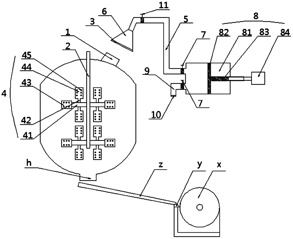
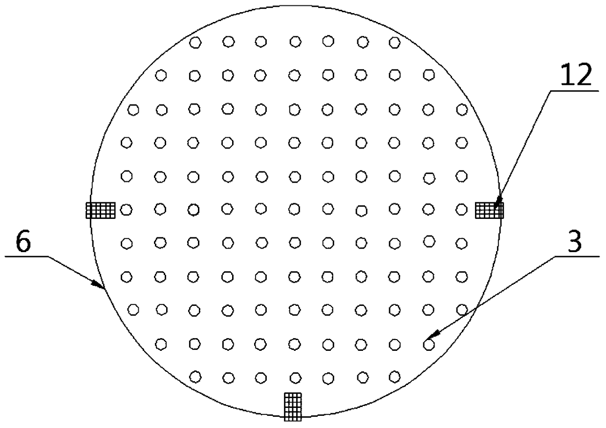
[0017] Such as figure 1 , 2 As shown, a PVC stabilizer stirring and slicing assembly line includes a dust suction device, a reaction kettle and a flaking machine x, wherein the top of the reactor is provided with a feeding port 1, and the bottom is provided with a discharge port h, and the flaking machine There is a storage tray y on x, and it is characterized in that: the flaker x is located under the reaction kettle, and the reaction kettle and the flaker x are connected by a diversion chute z, and the diversion chute The upper end of z is located below the discharge port h, and the lower end of the diversion chute z is located above the storage tray y.

[0018] The reactor is provided with a stirring main shaft 2, and the top of the stirring main shaft 2 protrudes from the reactor, and two sets of stirring paddles 4 are installed on the stirring sp...


PUM


Abstract

The invention discloses a PVC stabilizer stirring and slicing assembly line, which comprises a dust suction device, a reaction kettle and a flaking machine. The flake machine is located under the reaction kettle, and the reactor and the flake machine are connected through a diversion chute. The upper end of the diversion chute is located below the discharge port, and the lower end is located above the storage tray; the dust collection device includes a dust collection hood and an air extraction device. , the two are connected by a suction pipe, the dust cover is located above the feeding port, the air extraction device includes an air pump with a piston, the piston is connected to a piston rod, and one end of the piston rod extends out of the rear end of the air pump and is connected to the screw motor , one end of the dust suction pipe is connected to the front end of the air pump, a stirring spindle is arranged in the reactor, the upper part of the stirring spindle extends out of the reactor, and at least one set of stirring paddles is installed on the stirring spindle. Suction the powdery raw materials to avoid the flying of powdery raw materials and ensure the health and safety of workers.

Description

technical field [0001] The invention relates to the field of composite material processing, in particular to a PVC stabilizer stirring and slicing assembly line. Background technique [0002] Reactor is a comprehensive reaction vessel, which is widely used in petroleum, chemical, rubber, pesticide, dye, medicine, food and other production users and various scientific research and experimental projects. Reactor is widely used in petroleum, chemical, rubber, pesticide, pharmaceutical , food and other fields, it uses the stirring device to stir and mix the materials, so that the materials in the reactor can be distributed more evenly to accelerate the material reaction, and ensure that the materials in the reactor can carry out the predetermined chemical reaction according to the predetermined reaction conditions. In the field of processing, it is necessary to pour each raw material into the reactor for stirring and mixing when feeding, because the materials are all in the form...

Claims


Application Information

Patent Timeline
Patent Type & Authority Patents(China)
IPC IPC(8): B01D46/00B01D46/10B01J4/00B01J19/18
CPCB01D46/10B01J4/00B01J19/0066B01J19/18B01D2267/30B01J2219/185B01D46/56
Inventor 翁腾飞
Owner CHONGQING TAIYUE TECH
Why Eureka
Try Eureka