
Novel metal-free connector composite material sandwiched plate connecting structure and design method thereof

A composite material and connection structure technology, which is applied in the direction of chemical instruments and methods, synthetic resin layered products, layered products, etc., can solve the problems that cannot meet the use requirements, cannot realize electromagnetic wave stealth, and increase the thickness of the connection area.

Active Publication Date: 2016-04-20
NANJING UNIV OF TECH
View PDF3 Cites 9 Cited by
  • Summary
  • Abstract
  • Description
  • Claims
  • Application Information

AI Technical Summary

Problems solved by technology

[0005] The mechanical connection needs to drill holes in the connection area, and the opening causes delamination around the hole, resulting in lower extrusion strength in the connection area (the strength criterion for the design of composite bolted connections is extrusion strength), resulting in increased thickness and weight in the connection area. increase, so that the weight reduction effect of composite materials is greatly reduced
At the same time, the existence of pores leads to a decrease in the watertightness and airtightness of the structure, which cannot meet the normal use requirements.
The most important thing is that metal is a total reflection material, and the use of metal connectors cannot achieve electromagnetic wave stealth

Method used


Image

  • Novel metal-free connector composite material sandwiched plate connecting structure and design method thereof
  • Novel metal-free connector composite material sandwiched plate connecting structure and design method thereof
  • Novel metal-free connector composite material sandwiched plate connecting structure and design method thereof

Examples


Embodiment approach

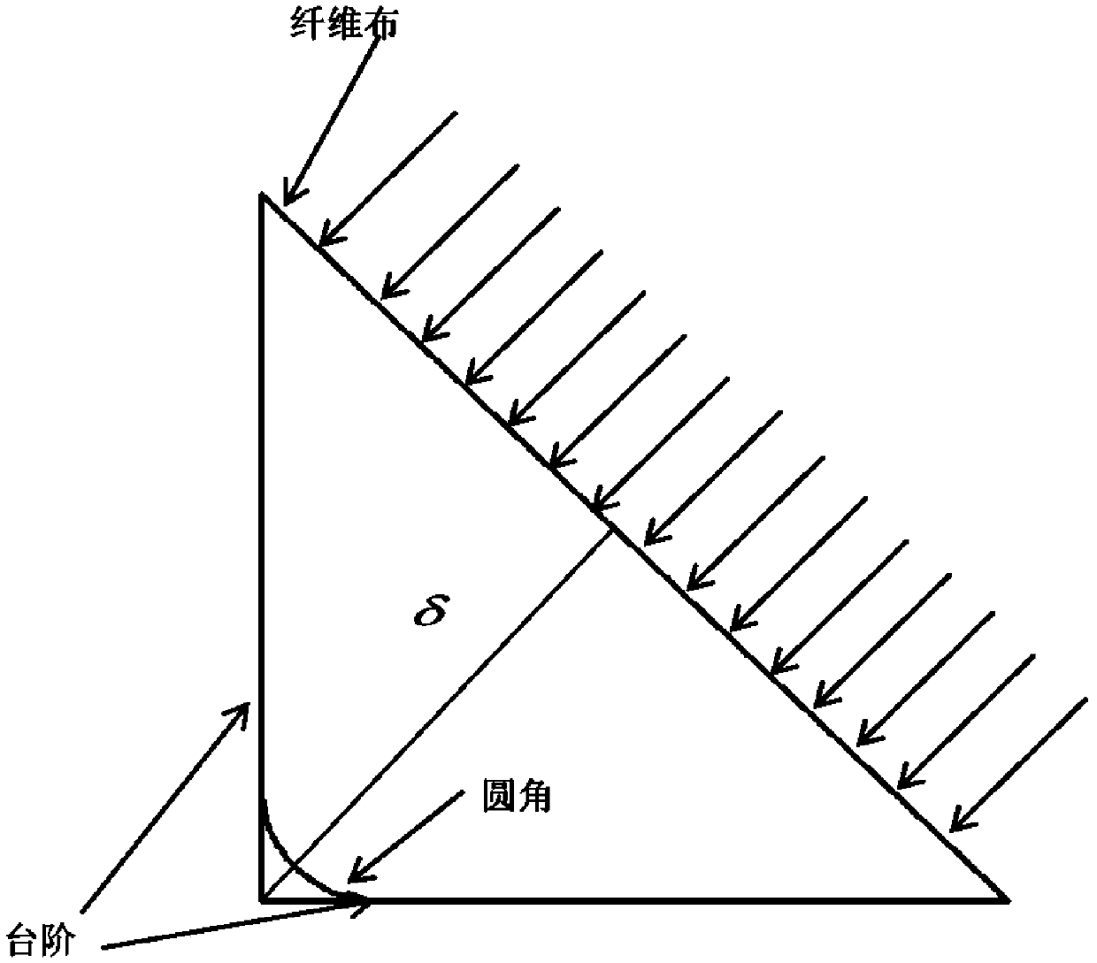
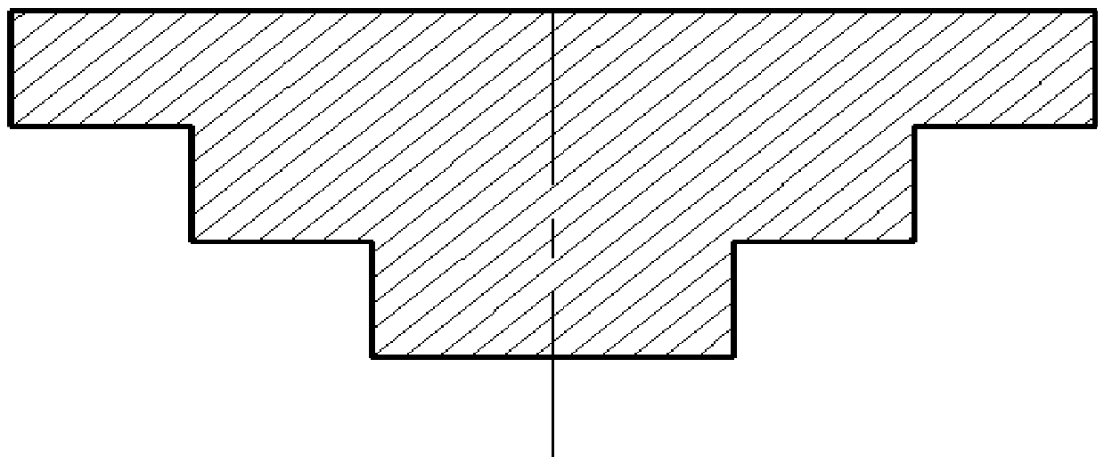
[0067] Such as Figure 1 to Figure 9 , a new type of composite sandwich panel connection structure without metal connectors, including glass fiber cloth 1A, PVC foam core 1B, composite sandwich panel 1, composite material connector 2 and composite material rib 3, glass fiber cloth 1A prepares composite sandwich panels 1, composite connectors 2 and composite reinforcement ribs 3 by cross-laminating PVC foam core 1B at 0 and 90 degrees, and prepares composite sandwich panel connection structures by secondary bonding.

[0068] A new composite sandwich panel connection structure without metal connectors, including glass fiber cloth 1A, PVC foam core 1B, composite sandwich panels 1, composite connectors 2 and composite ribs 3, composite sandwich panels 1 Covering and setting on the outer surface of the plate structure composed of glass fiber cloth 1A and PVC foam core 1B to form a sandwich panel unit structure, and the sandwich panel unit structure is connected by composite materia...


PUM


Abstract

The invention discloses a novel metal-free connector composite material sandwiched plate connecting structure and a design method thereof. The novel metal-free connector composite material sandwiched plate connecting structure is characterized by comprising glass fiber cloth (1A), a PVC foam core (1B), a composite material sandwiched plate (1), a composite material connector (2) and a composite material reinforcing rib (3), wherein the glass fiber cloth (1A) is layered in a crossed mode respectively at 0 degree and 90 degrees by surrounding the PVC foam core (1B) to prepare the composite material sandwiched plate (1), the composite material connector (2) and the composite material reinforcing rib (3), and a composite material sandwiched plate connecting structure is prepared by secondary bonding. The novel metal-free connector composite material sandwiched plate connecting structure can be used for structures with special requirements, such as high rigidity, high strength, and electromagnetic wave invisibility. Compared with a traditional connecting structure, the novel connecting structure disclosed by the invention has the characteristics of high connecting efficiency, compact structure, capability of meeting the electromagnetic invisibility requirement, simple and flexible molding technology and the like, and has wide application prospect in national defense and industrial equipment.

Description

technical field [0001] The invention relates to the technical field of full composite material sandwich structure connection, in particular to the metal-free connection technology of the same or a kind of composite material sandwich panels. Background technique [0002] Fiber-reinforced composite materials have a series of excellent properties such as high specific strength, high specific modulus, fatigue resistance, corrosion resistance, designability, low density, thermal expansion coefficient and good dimensional stability, and have been widely used in aviation, aerospace, and navigation. and other fields. [0003] Despite the continuous development of composite material forming technology, the integrity of composite material structure has been greatly improved. However, due to the technical level of composite material forming technology, structural requirements and road transportation requirements, composite material components are inevitably connected with parts. From ...

Claims


Application Information

Patent Timeline
IPC IPC(8): B32B27/30B32B17/02B32B17/10B32B3/28B32B3/06B32B33/00
CPCB32B3/06B32B3/28B32B17/02B32B17/10B32B27/304B32B33/00B32B2307/7242B32B2307/718B32B2307/7265B32B2307/50B32B2266/0235B32B2262/101
Inventor 陆晓峰曾卓朱晓磊刘杨刘路维
Owner NANJING UNIV OF TECH
Learn More