Preparation method of protective coating based on working surface of mould matrix

A technology for working surface and protective coating, applied in the field of preparation of protective coating, can solve the problems of low bonding strength, etc., and achieve the effects of good wear resistance and lubricity, simple and convenient operation, and improved bonding strength

Active Publication Date: 2016-04-20
AVIC BEIJING AERONAUTICAL MFG TECH RES INST
2 Cites 8 Cited by

AI-Extracted Technical Summary

Problems solved by technology

[0006] In order to solve the above technical problems, the object of the present invention is to provide a method for preparing a protective coating based on the working surface of the mold base, which can prepare a protective coating with high bonding strength, h...

Method used

Protective coating provided by the invention, the interface that its hard wear-resisting coating is connected with lubricating coating has the microstructure (micropore or microgroove) of inward depression, and hard wear-resisting in this microstructure There is a lubricating coating stored on the surface of the coating, so on the one hand, an effective connection is formed between the lubricating coating and the hard wear-resistant layer, which improves the bonding strength of the lubricating...

Abstract

The invention provides a preparation method of a protective coating based on a working surface of a mould matrix. The preparation method comprises the steps that 1) first paint is sprayed on the working surface of the mould matrix to form a hard wear-resistant coating; 2) an inward sunk microstructure is prepared on the surface of the hard wear-resistant coating; and 3) second paint is sprayed on the surface of the hard wear-resistant coating to form a lubricant coating, thereby accomplishing the preparation of the protective coating based on the working surface of the mould matrix. With the adoption of the preparation method, the protective coating having high bonding strength, wear resistance and lubricating property can be prepared on the working surface of the mould matrix, the problem that the interface bonding strength between the traditional hard wear-resistant layer and the traditional lubricant coating is low is solved, and the life of a mould is prolonged.

Application Domain

Technology Topic

Image

  • Preparation method of protective coating based on working surface of mould matrix
  • Preparation method of protective coating based on working surface of mould matrix
  • Preparation method of protective coating based on working surface of mould matrix

Examples

  • Experimental program(2)

Example Embodiment

[0034] Example 1
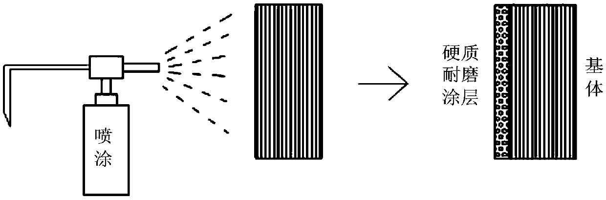
[0035] The invention provides a protective coating based on the working surface of a mold substrate. The preparation process of the coating is as follows figure 1 As shown, it includes the following steps:
[0036] 1) Cleaning of parts
[0037] Put the substrate to be processed in the acetone solution, and then put it into the ultrasonic cleaning test machine for ultrasonic cleaning, the cleaning time is 30 minutes; after the ultrasonic cleaning is completed, dry the substrate with a hair dryer and place it in the alcohol solution, and do it again Ultrasonic cleaning, the cleaning time is 30 minutes, and finally the substrate is blown dry with a hair dryer.
[0038] 2) Preparation of hard wear-resistant coating
[0039] Put the base material in the spraying workshop, fill the spray filler with an appropriate amount of SiC powder, and use low-temperature plasma spraying technology to spray (such as figure 2 As shown), a hard wear-resistant coating with a thickness of 200 μm is prepared on the working surface of the substrate by adjusting the spraying process parameters during the spraying process.
[0040] 3) Preparation of surface microstructure of hard wear-resistant coating
[0041] The laser drilling method is used to prepare micro-holes or micro-grooves of different shapes, spacings and depths on the surface of the hard wear-resistant coating, and the power density, pulse width, scan times, and speed of laser processing are adjusted for process control to make micro Holes or micro grooves are arranged in a periodic array on the surface of the hard wear-resistant coating (such as image 3 As shown), the aperture of the micropore or the groove width of the microgroove in the figure is a, and the distance between two adjacent micropores or microgrooves is b (the value of b is between 100μm-1mm). The depth of the hole or micro groove is d (the value of d is smaller than the thickness of the hard wear-resistant coating).
[0042] 4) Interface cleanup
[0043] Ultrasonic cleaning is performed on the surface of the processed hard wear-resistant coating, and defects and contaminants generated after laser processing are removed by ion beam bombardment and other post-processing methods.
[0044] 5) Preparation of lubricating coating
[0045] Put the base material in the spraying workshop, replace the spray powder, put the MoS 2 The powder is put into the spray coating port, and the lubricating coating is prepared by adjusting the spraying distance and the speed of the spray gun (the thickness of the lubricating coating is 200μm, such as Figure 4 As shown), the micropores or microgrooves are first filled in the preparation process, and then a lubricating coating with a thickness of 200 μm is prepared on the surface of the hard wear-resistant coating to complete the preparation of the protective coating.

Example Embodiment

[0046] Example 2
[0047] This embodiment provides a protective coating based on the working surface of the mold substrate. The preparation process of the layer is as follows: figure 1 As shown, it includes the following steps:
[0048] 1) Cleaning of parts
[0049] Put the substrate to be processed in the acetone solution, and then put it into the ultrasonic cleaning test machine for ultrasonic cleaning, the cleaning time is 30 minutes; after the ultrasonic cleaning is completed, dry the substrate with a hair dryer and place it in the alcohol solution, and do it again Ultrasonic cleaning, the cleaning time is 30 minutes, and finally the substrate is blown dry with a hair dryer.
[0050] 2) Preparation of hard wear-resistant coating
[0051] Put the substrate in the spraying workshop, fill the spray filler with an appropriate amount of alumina powder, and use low-temperature plasma spraying technology for spraying. During the spraying process, the working surface of the substrate can be hard-resistant with a thickness of 200μm by adjusting the spraying process parameters. Grind the coating.
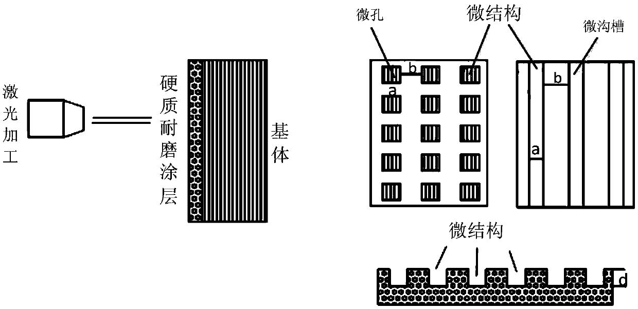
[0052] 3) Preparation of microstructure
[0053] The laser drilling method is used to prepare micro-holes or micro-grooves of different shapes, spacings and depths on the surface of the hard wear-resistant coating, and the power density, pulse width, scan times, and speed of laser processing are adjusted for process control, so that the micro Holes or microgrooves are arranged in a periodic array on the surface of the hard wear-resistant coating.
[0054] 4) Interface cleanup
[0055] Ultrasonic cleaning is performed on the surface of the processed hard wear-resistant coating, and defects and contaminants generated after laser processing are removed by ion beam bombardment and other post-processing methods.
[0056] 5) Preparation of lubricating coating
[0057] Put the base material in the spraying workshop, replace the spray powder, put the MoS 2 The powder is put into the spray coating port, and the lubricating coating is prepared by adjusting the spraying distance and the speed of the spray gun (the thickness of the lubricating coating is 200μm). The micropores or microgrooves are first filled in the preparation process, and then the hard A lubricating coating with a thickness of 200μm is prepared on the surface of the high-quality wear-resistant coating to complete the preparation of the protective coating.
[0058] Compare the protective coating provided by the present invention with traditional hard or lubricating coatings, such as Figure 5 As shown in the figure, it can be seen that: the traditional hard coating has no microstructure in the coating, so the friction coefficient of the coating is high during use, and it is easy to produce wear debris; while the traditional lubricating coating is in use In the middle, it is easy to form delamination at the interface, causing the coating to fail and fall off; these wear debris can easily interact with the coating surface repeatedly, affecting the lubricity of the workpiece during processing, and destroy the mold surface at the same time, accelerating the wear and tear;
[0059] The protective coating provided by the present invention has an inwardly concave microstructure (micropores or microgrooves) at the interface connecting the hard wear-resistant coating and the lubricating coating, and the microstructure is on the surface of the hard wear-resistant coating All have a lubricating coating, so on the one hand, an effective connection is formed between the lubricating coating and the hard wear-resistant layer, which improves the bonding strength of the lubricating coating and reduces the possibility of delamination; After the outer lubricating coating is consumed, these microstructures can still release the lubricating coating components to reduce the coefficient of friction between the workpiece and the mold and maintain lubricity. It can be seen that the protective coating provided by the present invention has better wear resistance and lubricity than traditional coatings, and the bonding fastness of each part of the coating is stronger.

PUM

PropertyMeasurementUnit
Thickness200.0µm
tensileMPa
Particle sizePa
strength10

Description & Claims & Application Information

We can also present the details of the Description, Claims and Application information to help users get a comprehensive understanding of the technical details of the patent, such as background art, summary of invention, brief description of drawings, description of embodiments, and other original content. On the other hand, users can also determine the specific scope of protection of the technology through the list of claims; as well as understand the changes in the life cycle of the technology with the presentation of the patent timeline. Login to view more.

Similar technology patents

Variable air volume laboratory temperature control system and method

PendingCN113834161AImprove the use effect and lifeEnsure smoothness and precisionMechanical apparatusSpace heating and ventilation safety systemsAutomatic controlAir volume
Owner:CHINA PETROLEUM & CHEM CORP +1

Heat dissipating device of electric welding machine

InactiveCN108568620ASolve the complex structure of air cooling and heat dissipationImprove the use effect and lifeDomestic cooling apparatusLighting and heating apparatusPositive currentEngineering
Owner:天津市金博阳热传电子技术有限公司

Solar energy and wind energy non-interfering street lamp

InactiveCN103292244AImprove the use effect and lifeOutdoor lightingWith built-in powerPhysicsEngineering
Owner:HUNAN BAOLI OPTOELECTRONICS TECH

A high temperature resistant filter cloth

InactiveCN102274657AStrong high temperature resistanceImprove the use effect and lifeWoven fabricsFiltration separationWeft yarnEngineering
Owner:DALIAN HUALONG FILTER CLOTH

Classification and recommendation of technical efficacy words

  • Improve the use effect and life
  • Good lubricity and wear resistance

Variable air volume laboratory temperature control system and method

PendingCN113834161AImprove the use effect and lifeEnsure smoothness and precisionMechanical apparatusSpace heating and ventilation safety systemsAutomatic controlAir volume
Owner:CHINA PETROLEUM & CHEM CORP +1

Solar energy and wind energy non-interfering street lamp

InactiveCN103292244AImprove the use effect and lifeOutdoor lightingWith built-in powerPhysicsEngineering
Owner:HUNAN BAOLI OPTOELECTRONICS TECH

A high temperature resistant filter cloth

InactiveCN102274657AStrong high temperature resistanceImprove the use effect and lifeWoven fabricsFiltration separationWeft yarnEngineering
Owner:DALIAN HUALONG FILTER CLOTH

Heat dissipating device of electric welding machine

InactiveCN108568620ASolve the complex structure of air cooling and heat dissipationImprove the use effect and lifeDomestic cooling apparatusLighting and heating apparatusPositive currentEngineering
Owner:天津市金博阳热传电子技术有限公司

Portable intelligent cervical vertebra recovery and treatment apparatus and mobile phone APP control method thereof

PendingCN109394406AHigh mechanical strength and stiffnessGood lubricity and wear resistanceFractureVertebraSpeech sound
Owner:尚鹏
Why Eureka
Try Eureka