Hydraulic system of overflow-loss-free loader and control method of hydraulic system

A technology of hydraulic system and overflow loss, applied in the direction of earth mover/shovel, mechanically driven excavator/dredger, construction, etc. Scale promotion and other issues to achieve the effect of improving energy utilization, strong anti-pollution ability, and improving fuel economy

Inactive Publication Date: 2016-04-20
JILIN UNIV
View PDF7 Cites 5 Cited by
  • Summary
  • Abstract
  • Description
  • Claims
  • Application Information

AI Technical Summary

Problems solved by technology

In small and medium-sized loaders, the working hydraulic system generally uses a quantitative pump, which is likely to cause a mismatch between the pump and the load demand flow, resulting in overflow loss, resulting in a decrease in fuel economy and an increase in oil temperature
Variable pumps are generally used in the working hydraulic system of large loaders, which are expensive and the hydraulic parts are sensitive to pollution
In order to ensure that the steering hydraulic system can still quickly perform full steering and improve production efficiency when the engine is idling, a large displacement quantitative pump is generally used, but a large amount of power loss will occur when the engine is at high speed
[0003] At present, the energy-saving technologies mainly used in the product include double-pump confluence technology and double-pump confluence equivalent unloading technology, but neither of them has completely solved the overflow problem, so the energy-saving effect is very limited
Komatsu has applied confluence technology in the flow amplifying valve of the steering system of its loader, but the technology is difficult and costly, and cannot be promoted on a large scale
Although variable displacement pump technology can reduce power loss, it is currently difficult to popularize due to its high cost

Method used


Image

  • Hydraulic system of overflow-loss-free loader and control method of hydraulic system
  • Hydraulic system of overflow-loss-free loader and control method of hydraulic system
  • Hydraulic system of overflow-loss-free loader and control method of hydraulic system

Examples


Embodiment Construction

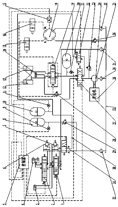
[0020] see figure 1 , is an embodiment of the present invention, the system is composed of an engine, a transmission shaft, a filter, a fuel tank, a quantitative pump, a three-position four-way reversing valve, a two-position three-way reversing valve, an accumulator, a steering gear, and a steering limiter. Position valve, flow amplification valve, steering cylinder, safety valve, sensor, one-way valve, double-acting safety valve, multi-way valve, bucket cylinder, boom cylinder and controller. The accumulator includes a high-pressure accumulator 8, a low-pressure accumulator 10 and a steering accumulator 20; the steering limit valve includes a left steering limiting valve 15 and a right steering limiting valve 16; the flow amplifying valve Including the first three-position four-way reversing valve 19, or the gate type shuttle valve 14 and the second safety valve 28; the sensor includes the first pressure sensor 9, the second pressure sensor 11, the third pressure sensor 21 a...


PUM


Abstract

The invention discloses a hydraulic system of an overflow-loss-free loader and a control method of the hydraulic system. On the basis of an original hydraulic system of the loader, parts like energy accumulators, reversing valves, sensors and a controller are additionally mounted, and part simplification is performed; through corresponding control strategies, matching between output flow of a fixed displacement pump and needed flow of a load (an external load and the energy accumulator) can be realized, overflow loss can be avoided completely, and throttling loss and friction loss can be reduced; potential energy recycled is used for being provided to a steering gear, a multi-pump hydraulic system of the loader is changed into a single-pump hydraulic system, and energy is stored through the energy accumulator, so that pressure buildup time of the hydraulic system and installed power of an engine are reduced, and efficiency of the whole loader is improved. The energy accumulator is utilized to absorb pressure impact, so that stability and reliability of the hydraulic system are improved while fatigue lives of elements are prolonged.

Description

technical field [0001] The invention relates to the technical field of engineering machinery, in particular to an energy-saving hydraulic system and a control method for a loader without overflow loss Background technique [0002] Loader is a widely used engineering machinery, hydraulic system is an important part of it, generally composed of working hydraulic system and steering hydraulic system. In small and medium-sized loaders, the working hydraulic system generally uses a quantitative pump, which is likely to cause a mismatch between the flow of the pump and the load demand, resulting in overflow loss, resulting in a decrease in fuel economy and an increase in oil temperature. The working hydraulic system of large loaders generally uses variable displacement pumps, which are expensive and the hydraulic parts are sensitive to pollution. In order to ensure that the steering hydraulic system can still quickly perform full steering and improve production efficiency when th...

Claims


Application Information

Patent Timeline
Patent Type & Authority Applications(China)
IPC IPC(8): E02F9/22E02F3/42
CPCE02F3/42E02F9/2217
Inventor 王继新张宇韩云武高靖杨永海范久臣韩燊睿李新华
Owner JILIN UNIV
Why Eureka
Try Eureka