Winding pipe

A winding pipe and spiral winding technology, which is applied in the direction of hoses, pipes, pipes/pipe joints/pipe fittings, etc., can solve the problems of affecting the service life of pipes, insufficient welding, high operating costs, etc., and achieve good spring elasticity and pressure bearing capacity Good, the effect of simplifying the production process

Inactive Publication Date: 2016-04-20
NINGBO YINZHOU QIUAI JIELI PLASTIC FACTORY
View PDF10 Cites 5 Cited by
  • Summary
  • Abstract
  • Description
  • Claims
  • Application Information

AI Technical Summary

Problems solved by technology

When the above process is carried out in the final heating step, if the temperature is too high, it will easily cause the inner layer of the pipe and / or the outer layer of the pipe to melt through, and if the temperature is too low, it will easily cause the fusion of the two to be insufficient; Or the outer layer of the pipe will cause melting, usually the outer circumference of the steel wire reinforcement will be coated with adhesive in advance; at the same time, the plastics of the inner and outer layers of the pipe will be deformed during the heating process, so that the inner wall of the finally prepared threaded winding pipe and the The outer wall has corrugated grooves. Such pipes are used in vacuum cleaners, ventilation devices, and drainage equipment. The storage will cause debris to remain in the pipe, and the long-term existence of residual debris will corrode the inner wall of the pipe, which will still affect the service life of the pipe. Affect
[0011] In addition, in the prior art, the inner layer, the rib layer and the outer layer of the wound pipe are all wound separately, that is, the three layers belong to separate structures, and the rib layer is only covered by the connection between the inner layer and the outer layer. , the equipment required for preparation is more complex and the operating cost is higher

Method used


Image

  • Winding pipe
  • Winding pipe
  • Winding pipe

Examples


Embodiment Construction

[0026] The present invention will be further described in detail below in conjunction with the accompanying drawings and embodiments.

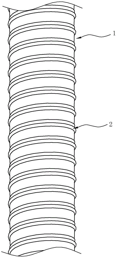
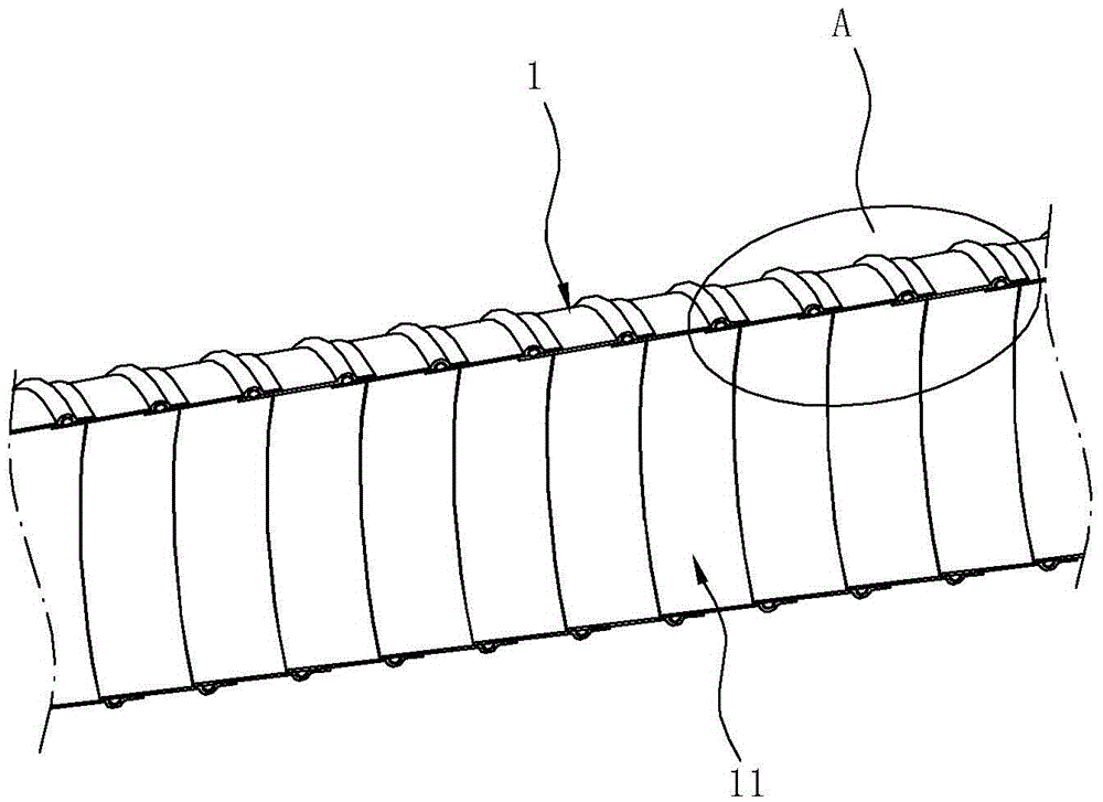
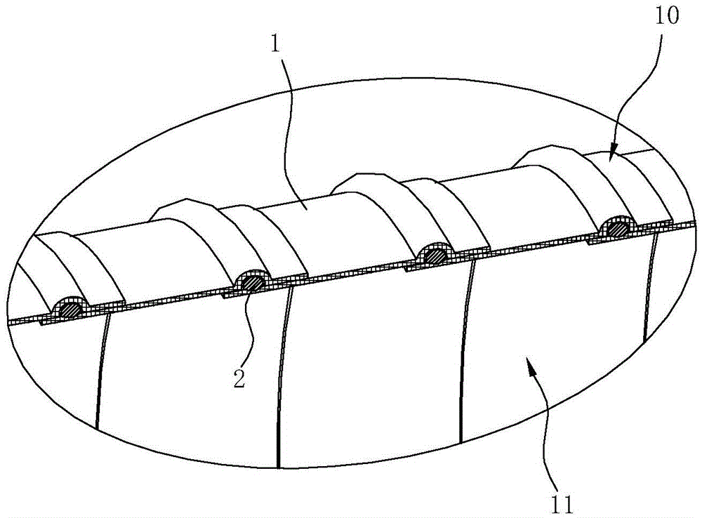
[0027] Such as Figure 1~3 As shown, the winding pipe of this embodiment includes a plastic layer 1 and a reinforcing rib 2 covered in the plastic layer 1. The plastic layer 1 is formed by spirally winding a plastic sheet 100, and two adjacent turns of plastic are formed during the winding process. The sheets 100 are overlapped and fused at the edges to form a spiral overlapping area 10 on the plastic layer 1, and the reinforcing rib 2 is formed into a spring matching the shape of the overlapping area 10 and embedded in the above overlapping area 10 . The plastic layer 1 in this embodiment is formed by winding a piece of plastic sheet 100 under the continuous rotation of the roller mold. The roller mold supports the inner side of the plastic layer 1 during the rotation process, and the plastic layer 1 forms a smooth surface. The inner wall 1...


PUM


Abstract

The invention relates to a winding pipe which comprises a plastic layer and a stiffening rib coated in the plastic layer. The winding pipe is characterized in that the plastic layer is formed by spirally winding a plastic sheet; every two adjacent rings of plastic sheet are mutually overlapped and fused at the edges, so that a spiral overlapping region is formed on the plastic layer; and the stiffening rib is in the shape of a spiral spring matched with the overlapping region and is embedded in the overlapping region. The winding pipe is simple in overall structure, and is formed by winding only one plastic sheet and one stiffening rib, so that the prepared pipe body has smooth inner wall; and thus, dust, foreign bodies and the like can not be easily accumulated in the use process. The stiffening rib is just positioned in the overlapping region of the plastic sheet, and the inner layer plastic sheet and outer layer plastic sheet in the high temperature state are completely fused, so that the winding pipe has the advantages of firm overall structure and longer service life. According to the winding pipe, the adhesive layer does not need to be previously coated on the periphery of the stiffening rib, and the spring formed by the stiffening rib has favorable elasticity, so that the pipe body has high strength and favorable pressure bearing capacity.

Description

technical field [0001] The invention relates to a winding pipe, in particular to a plastic pipe with reinforcing ribs winding. Background technique [0002] Plastic hoses commonly used in vacuum cleaners, ventilation devices, range hoods, and drainage equipment are mostly obtained by extrusion or blow molding. Such plastic hoses are simple to manufacture and low in production cost, but they are pressure-resistant and resistant The ability is also poor, so people improve its pressure bearing and pressure resistance by embedding reinforcing ribs in the plastic hose. [0003] The Chinese utility model patent "Plastic Steel Winding Pipe" (application number: CN201220334432.2) with the authorized announcement number CN202674804U discloses a structure, which includes a polyethylene inner pipe, a winding layer and a polyethylene outer protective layer. The winding layer is made of high Made of high-strength plastic steel wire, the winding layer in the above-mentioned winding pipe ...

Claims


Application Information

Patent Timeline
Patent Type & Authority Applications(China)
IPC IPC(8): F16L11/24
CPCF16L11/24
Inventor 林和平
Owner NINGBO YINZHOU QIUAI JIELI PLASTIC FACTORY
Why Eureka
Try Eureka