Free-surface secondary reflection concentrator system for efficient solar energy thermal/electric conversion

A solar thermal and concentrating system technology, applied in the field of concentrating systems, can solve the problems of not being able to receive all the light spots, limited entrance area of ​​the heat-absorbing cavity, waste of resources, etc.

Active Publication Date: 2016-04-20
HARBIN INST OF TECH
View PDF6 Cites 8 Cited by
  • Summary
  • Abstract
  • Description
  • Claims
  • Application Information

AI Technical Summary

Problems solved by technology

[0003] The present invention aims to solve the technical problem that the entrance area of ​​the heat-absorbing cavity of the traditional solar dish-type concentrating system is limited, and cannot receive all the energy of the light spot, which will be intercepted, resulting in waste of resources. Free-surface secondary reflection concentrating system for solar heat / electricity efficient conversion

Method used


Image

  • Free-surface secondary reflection concentrator system for efficient solar energy thermal/electric conversion
  • Free-surface secondary reflection concentrator system for efficient solar energy thermal/electric conversion
  • Free-surface secondary reflection concentrator system for efficient solar energy thermal/electric conversion

Examples


specific Embodiment approach 1

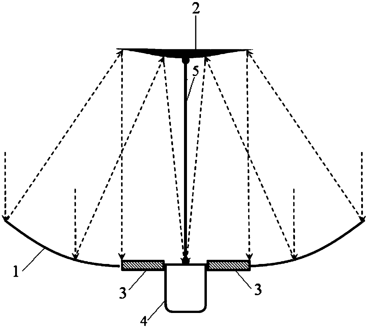
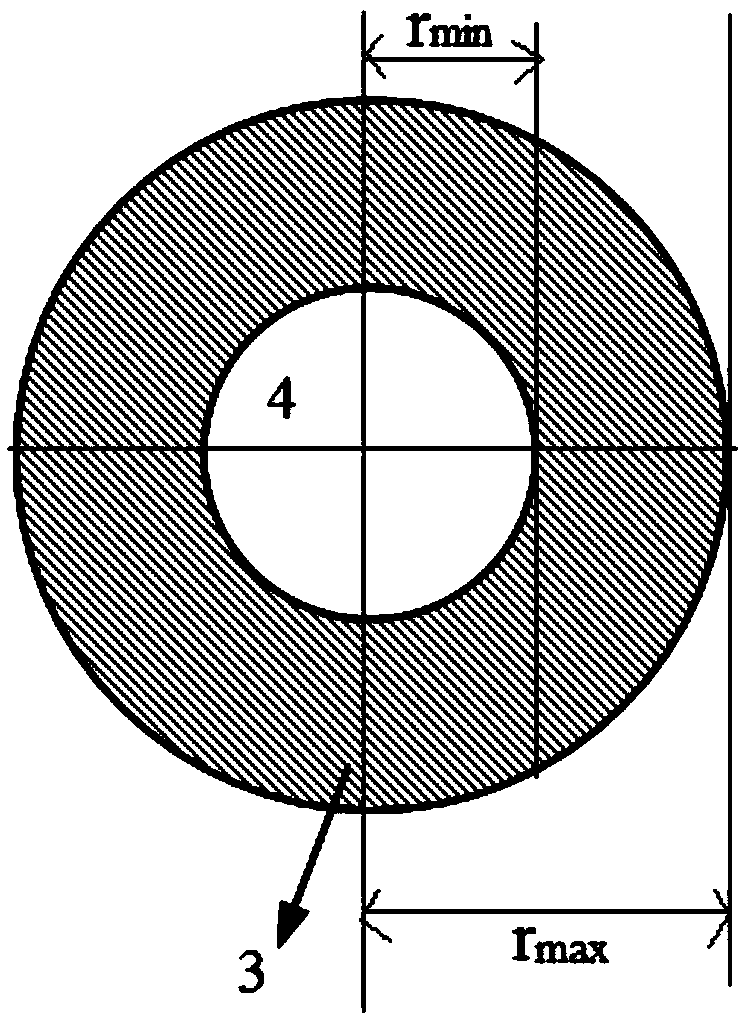
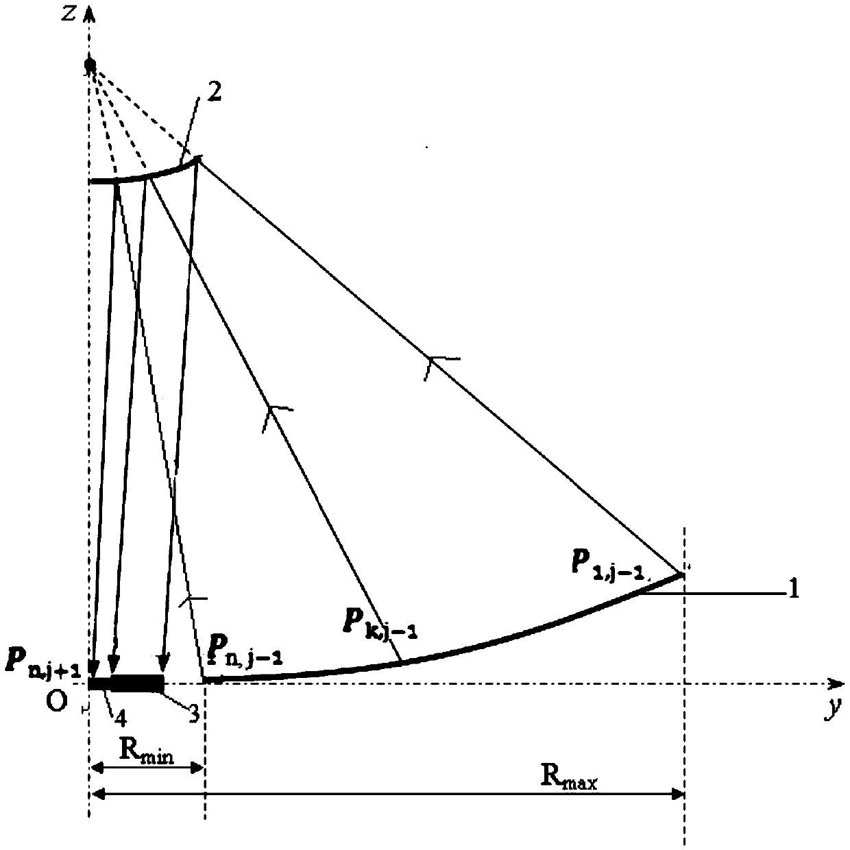
[0061] Specific Embodiment 1: This embodiment is a free-surface secondary reflection and concentrating system for solar thermal / electrical high-efficiency conversion, using a free-surface Cassegrain reflection and concentrating system, consisting of a primary mirror 1, a secondary mirror 2 and The receiver is composed of; the primary mirror 1, the secondary mirror 2 and the receiver are all axisymmetric structures, and the primary mirror 1, the secondary mirror 2 and the receiver are coaxial; the primary mirror 1 and the secondary mirror 2 are connected by a bracket 5 , the concave surface of the primary mirror 1 faces the secondary mirror 2, the receiver is fixed on the bracket 5, and the bracket 5 is arranged on the axis of the primary mirror 1, the secondary mirror 2 and the receiver; the receiver is composed of the heat absorber 4 and The concentrating photovoltaic cell panel 3 is composed of a flange, the flange is installed on the optical window end of the heat absorber 4...

specific Embodiment approach 2

[0100] Embodiment 2: The difference between this embodiment and Embodiment 1 is that the receiver is installed at the intersection of the bracket 5 and the primary mirror 1 . Others are the same as the first embodiment.

specific Embodiment approach 3

[0101] Embodiment 3: The difference between this embodiment and Embodiment 1 or 2 is that the receiver is installed on the bracket 5 and the distance from the primary mirror 1 is 1 / 4 of the length of the bracket 5 . Others are the same as those in Embodiment 1 or 2.


PUM


Abstract

The invention relates to a concentrator system for efficient solar energy thermal/electric conversion, in particular to a free-surface secondary reflection concentrator system for efficient solar energy thermal/electric conversion. The invention aims at solving the technical problem that at present, the area of an entrance of a heat absorption cavity of the traditional solar dish type concentration system is limited, so that the traditional solar dish type concentration system is not capable of receiving the energy of all light spots and can intercept the energy of the light spots; therefore, resource waste is caused. The free-surface secondary reflection concentrator system for efficient solar energy thermal/electric conversion comprises a primary mirror, a secondary mirror and a receiver, wherein the primary mirror, the secondary mirror and the receiver respectively have an axisymmetric structure and are arranged coaxially; the receiver consists of a heat absorber, a concentrating photovoltaic cell panel and a flange; the concentrating photovoltaic cell panel is arranged at the outer side of the flange; a free-form surface of the secondary mirror is determined as follows: 1, dissociaton of a starting point and a target point; 2, solution of discrete points of the free-form surface of the secondary mirror; 3, drawing of the surface of the secondary mirror. The free-surface secondary reflection concentrator system for efficient solar energy thermal/electric conversion is applied to the field of solar energy.

Description

technical field [0001] The invention relates to a light concentrating system for solar heat / electricity high-efficiency conversion. Background technique [0002] With the continuous development of precision machining technology and the arrival of new 3D printing technology, the design of advanced optical systems has become more efficient and flexible. Compared with traditional methods, free-form surfaces have higher design freedom and flexible space layout, making The design of the optical system is simplified, giving it the advantages of compact structure, high utilization rate and energy saving. Different from the traditional optical system, the free-surface optical system does not have a specific surface equation, and it cannot be defined by the equation formula. The free-form surface is often composed of many space points, and then the non-uniform rational B-spline (NURBS) curves or other methods for connection reconstruction to finally obtain the space surface. The te...

Claims


Application Information

Patent Timeline
Patent Type & Authority Applications(China)
IPC IPC(8): F24J2/07F24J2/12H02S40/44F24S20/20F24S23/71
CPCF24S20/20F24S23/71F24S2023/87H01L31/042Y02E10/40Y02E10/50
Inventor 夏新林孟宪龙孙创艾青陈学
Owner HARBIN INST OF TECH
Why Eureka
Try Eureka