Device and system for measuring orbital angular momentum spectrum of light beam
A technology of orbital angular momentum and incident light beams, which is applied in the field of optoelectronics, can solve the problems of difficult resolution of light spots and increase the complexity of spectrum measurement, and achieve the effect of simplifying the number of devices, simple structure, fast and accurate measurement
- Summary
- Abstract
- Description
- Claims
- Application Information
AI Technical Summary
Problems solved by technology
Method used
Image
Examples
Embodiment 1
[0049] Embodiment 1: Measurement of the orbital angular momentum spectrum of a vortex beam whose orbital angular momentum components are respectively +4 order and -4 order and the ratio is 1:1.
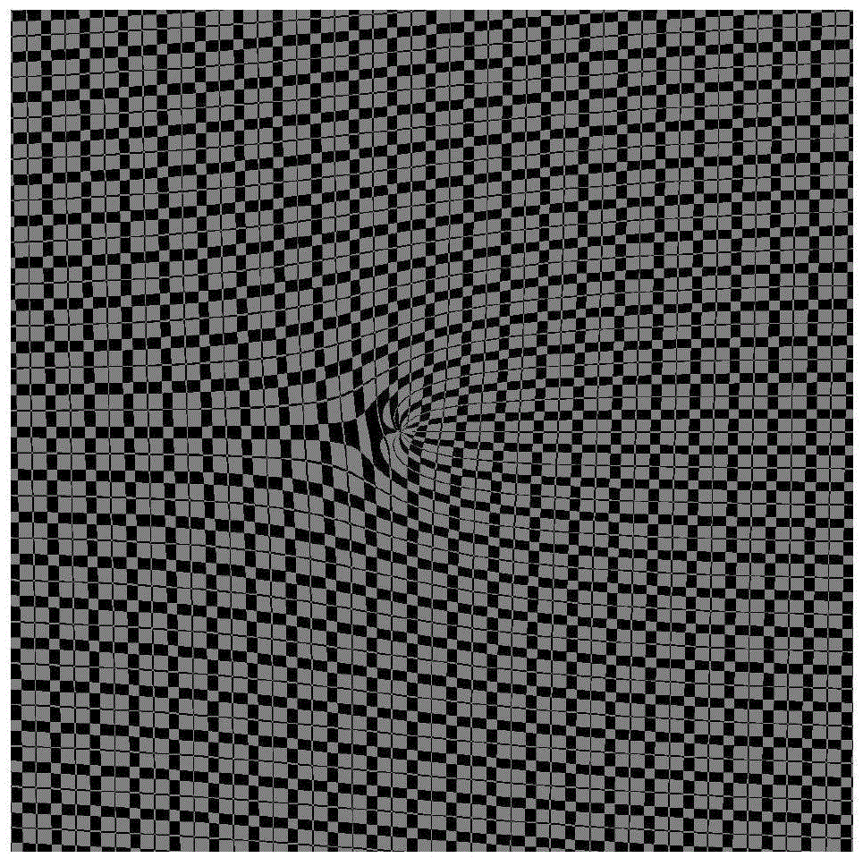
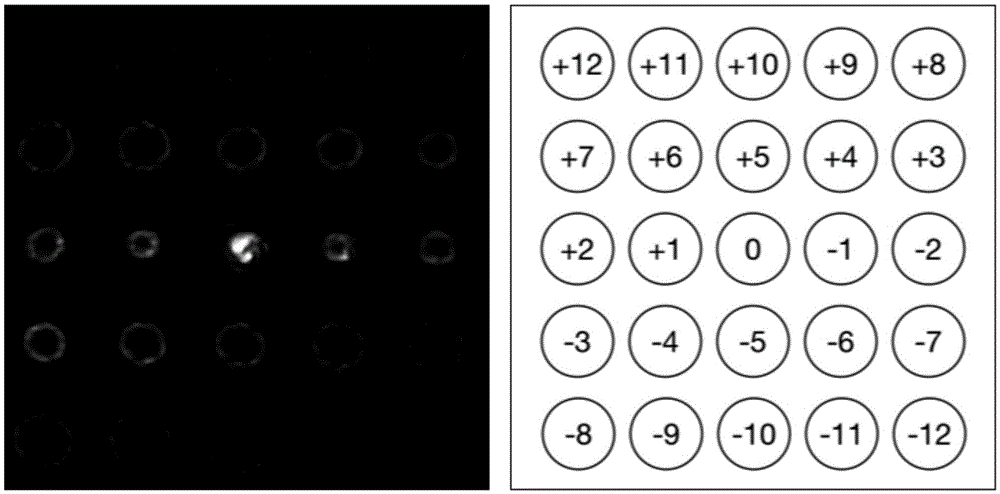
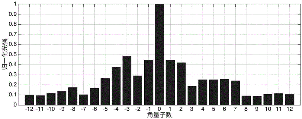
[0050] Figure 5(a) shows the light field distribution of the vortex beam with orbital angular momentum components of +4 order and -4 order and a ratio of 1:1, and its gray diffraction spot after passing through the Damman vortex grating. Referring to Figure 2(a), it can be seen from the diffracted light field that the incident beam contains +4th order and -4th order orbital angular momentum components. The grayscale image of the diffracted light field is transmitted from the measurement optical system to the host through the data transmission part, and the system in the host that directly obtains the orbital angular momentum spectrum based on the far-field diffraction light field of the Damman vortex grating is shown in Figure 5(a) The grayscale diffraction spot is analyzed. In this ...
Embodiment 2
[0051] Embodiment 2: Measurement of the orbital angular momentum spectrum of a vortex beam whose orbital angular momentum components are respectively +4 order and -4 order and the ratio is 1:2.
[0052] Figure 6(a) shows the light field distribution of a vortex beam whose orbital angular momentum components are +4 and -4 and the ratio is 1:1, and its gray diffraction spot after passing through the Damman vortex grating. Referring to Figure 2(a), it can be seen from the diffracted light field that the incident beam contains +4th order and -4th order orbital angular momentum components. The grayscale image of the diffracted light field is transmitted from the measurement optical system to the host computer through the data transmission part, and the system in the host computer that directly obtains the orbital angular momentum spectrum based on the far-field diffraction light field of the Damman vortex grating is shown in Figure 6(a) The grayscale diffraction spot is analyzed. ...
Embodiment 3
[0053] Embodiment 3: Measurement of the orbital angular momentum spectrum of a vortex beam whose orbital angular momentum components are respectively -9 order, -2 order and +6 order and the ratio is set randomly.
[0054] Fig. 7(a) shows the light field distribution of the vortex beam whose orbital angular momentum components are -9 order, -2 order and +6 order and the ratio is set randomly, and its gray level after passing through the Damman vortex grating Diffraction spots. Referring to Figure 2(a), it can be seen from the diffracted light field that the incident light beam contains -9 order, -2 order and +6 order orbital angular momentum components. The grayscale image of the diffracted light field is transmitted from the measurement optical system to the host computer through the data transmission part, and the system in the host computer that directly obtains the orbital angular momentum spectrum based on the far-field diffraction light field of the Damman vortex grating ...
PUM
 Abstract
Description
Claims
Application Information
 - R&D
- Intellectual Property
- Life Sciences
- Materials
- Tech Scout
- Unparalleled Data Quality
- Higher Quality Content
- 60% Fewer Hallucinations
Browse by: Latest US Patents, China's latest patents, Technical Efficacy Thesaurus, Application Domain, Technology Topic, Popular Technical Reports.
© 2025 PatSnap. All rights reserved.Legal|Privacy policy|Modern Slavery Act Transparency Statement|Sitemap|About US| Contact US: help@patsnap.com


