Device for low resistance conduction

A low-resistance and conduction technology, applied in the direction of measuring electricity, measuring electrical variables, measuring devices, etc., can solve the problems of false alarms and inaccurate low-resistance conduction tests, so as to avoid false alarms and avoid measurement accuracy The effect of reducing and reducing the deviation

Inactive Publication Date: 2016-04-20
HUBEI SANJIANG AEROSPACE HONGFENG CONTROL
View PDF12 Cites 1 Cited by
  • Summary
  • Abstract
  • Description
  • Claims
  • Application Information

AI Technical Summary

Problems solved by technology

[0008] Aiming at the defects of the prior art, the present invention provides a low-resistance conduction testing device, which solves the problem of inaccuracy and prone to false alarms in the current low-resistance conduction test by setting improved circuit units and optimized circuit structures. question

Method used


Image

  • Device for low resistance conduction
  • Device for low resistance conduction
  • Device for low resistance conduction

Examples


Embodiment Construction

[0024] In order to make the technical scheme, technical purpose and technical effect of the present invention clearer, the present invention will be described in further detail in conjunction with specific examples. It should be noted that the following examples are only illustrative and do not constitute a limitation of the present invention .

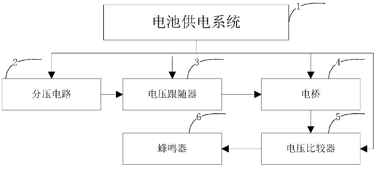
[0025] figure 1 It is a block circuit diagram of a low-resistance conduction testing device according to an embodiment of the present invention, such as figure 1 As shown, the low-resistance conduction test equipment includes a voltage divider circuit 2, a voltage follower 3, a bridge 4, a voltage comparator 5, a buzzer 6 and a power supply system 1 for supplying power to each module.

[0026] Wherein, the input end of the voltage follower 3 is connected to the output end of the voltage divider circuit 2, the input end of the electric bridge 4 is connected to the output end of the voltage follower 3, and the input end of the voltage ...


PUM


Abstract

The invention discloses a test device for low resistance conduction. The test device is used for conduction tests of low resistance. The test device is characterized in that the test device includes a battery power supply system, a voltage dividing circuit, a voltage follower, a voltage comparator, a bridge circuit and a buzzer; the output end of the battery power supply system is connected with the inputs end of the voltage dividing circuit, the voltage follower and the bridge circuit; the input end of the voltage follower is connected with output end of the voltage dividing circuit; the input end of the bridge is connected with the output end of the voltage follower; the input end of the voltage comparator is connected with the output end of the bridge; and the output end of the buzzer is connected with the input end of the voltage comparator. The test device of the invention is mainly used for conduction tests of printed wires and cables. With the device adopted, false alarm faults caused by large maximum on resistance of a multimeter can be eliminated, and the reliability of conduction detection can be improved. The test device has the advantages of portable convenience and convenience in battery replacement.

Description

technical field [0001] The invention relates to the field of instruments and equipment, in particular to a low-resistance conduction test device, which is suitable for the conduction test of printed boards and cables. Background technique [0002] After the product is assembled, it is generally necessary to conduct a continuity test on the internal connection harness before it is officially powered on to ensure the reliability and stability of the line connection and avoid product damage due to wire welding errors when the product is officially powered on. [0003] At present, the three-purpose meter is generally used as the instrument and equipment for the conduction test. For the conduction test, the three-purpose meter generally includes a voltage comparison circuit, an amplifier circuit, and a buzzer circuit. Through calculation, the threshold resistance of the measured resistance is obtained. When measuring The two ends of the test pen of the three-purpose meter are con...

Claims


Application Information

Patent Timeline
Patent Type & Authority Applications(China)
IPC IPC(8): G01R31/02
CPCG01R31/50
Inventor 邹力刘江龙邓世恒陈地周伟
Owner HUBEI SANJIANG AEROSPACE HONGFENG CONTROL
Why Eureka
Try Eureka