Check patentability & draft patents in minutes with Patsnap Eureka AI!

Signal loop detection circuit and method

A detection circuit and signal ring technology, applied in the direction of measuring electricity, measuring electrical variables, electronic circuit testing, etc., can solve the problem that the chip initialization configuration information does not want to be changed, etc.

Active Publication Date: 2016-04-20
AMICRO SEMICON CORP
View PDF7 Cites 2 Cited by
  • Summary
  • Abstract
  • Description
  • Claims
  • Application Information

AI Technical Summary

Problems solved by technology

However, during the use stage, the initial configuration information of the chip does not want to be changed, so as not to affect the normal function of the chip

Method used


Image

  • Signal loop detection circuit and method
  • Signal loop detection circuit and method

Examples


Embodiment Construction

[0014] Embodiments of the present invention will be described in detail below in conjunction with the accompanying drawings.

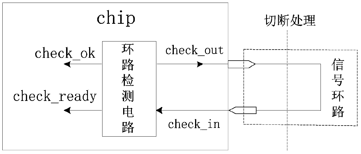
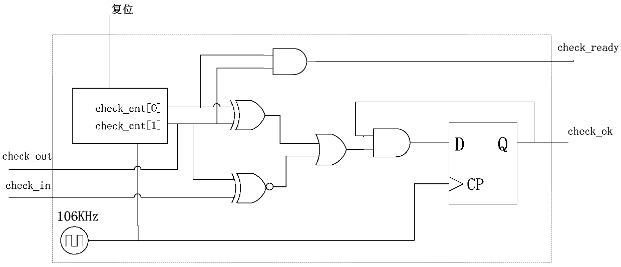
[0015] Such as figure 1 and figure 2 As shown, the signal loop detection circuit provided in this embodiment is used to detect the integrity of the signal loop of the integrated circuit when it is powered on or started, and includes a clock unit, a counter and a logic operation circuit. The logic operation circuit includes an exclusive OR gate, an exclusive NOR gate, an OR gate, a first AND gate, a second AND gate and a D flip-flop.

[0016] The clock unit provides the clock for the counter. The counter is a two-bit counter. The low-order count signal check_cnt[0] and the high-order count signal check_cnt[1] of the counter are respectively connected to the two inputs of the XOR gate, and the high-order count signal check_cnt[1] is also used as The output detection signal check_out is connected to the input terminal of the signal loop; the two input ...


PUM


Abstract

The invention discloses a signal loop detection circuit and method. A specific counting signal sequence is generated through a counter and an ingenious logical operation circuit is matched, counting signals sequentially are 01, 00, 10 and 11, and the logical operation circuit is such designed that when an integrated circuit is powered on or started, a control signal that is output check_ok=1; when a signal loop is in a complete state, after detection is completed, the control signal that is output check_ok=1; when the signal loop is in a cutoff state, after detection is completed, the control signal that is output check_ok=0; and only when the counting signal of the counter is 11, a detection completion signal that is output check_ready=1, and at this moment the control signal that is output check_ok is valid. The signal loop detection circuit can detect whether the signal loop is complete when the integrated circuit performs initialized information configuration, enters different working modes, and then chooses to load different configuration information.

Description

technical field [0001] The present invention relates to the technical field of electronic circuits, in particular to a detection circuit and a method for detecting the integrity of an integrated circuit signal loop when powering on or starting. Background technique [0002] As we all know, due to the slight difference in the production process of the same chip, the performance of the chip in different production batches will be different, which will affect the function of the chip, resulting in a very low yield rate of the chip. In the testing phase, the chip's performance and yield can be improved by adjusting the initial configuration parameters of the chip. However, during the use stage, the initial configuration information of the chip is not expected to be changed, so as not to affect the normal function of the chip. In this way, we hope to open the modification authority of the chip initialization configuration parameters during the production test phase, and prohibit...

Claims


Application Information

Patent Timeline
IPC IPC(8): G01R31/28
CPCG01R31/2851
Inventor 赵旺
Owner AMICRO SEMICON CORP
Features
  • R&D
  • Intellectual Property
  • Life Sciences
  • Materials
  • Tech Scout
  • Unparalleled Data Quality
  • Higher Quality Content
  • 60% Fewer Hallucinations
Learn More