Power module low-inductance lead terminal

A technology of lead terminals and power modules, applied in the field of low inductance lead terminals of power modules, can solve the problems of increasing the operating frequency and switching speed of the module, large parasitic inductance of the module, and failure of the chip, and achieves the effect of reducing the parasitic inductance

Inactive Publication Date: 2016-04-20
南京银茂微电子制造有限公司
View PDF5 Cites 14 Cited by
  • Summary
  • Abstract
  • Description
  • Claims
  • Application Information

AI Technical Summary

Problems solved by technology

Since the withstand voltage of the power chip has a certain limit, if the current changes too fast when the module is switched on, the chip voltage will be too high, resulting in chip failure
[0004] In the existing power module, due to the design problem of the lead terminal structure, the module has a large parasitic inductance, which limits the further improvement of the module's operating frequency and switching speed

Method used


Image

  • Power module low-inductance lead terminal
  • Power module low-inductance lead terminal
  • Power module low-inductance lead terminal

Examples


Embodiment Construction

[0028] In order to deepen the understanding of the present invention, the present invention will be further described below in conjunction with the accompanying drawings and embodiments, which are only used to explain the present invention and do not limit the protection scope of the present invention.

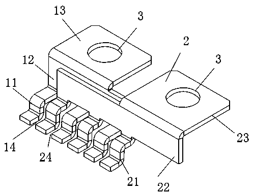
[0029] like Figure 5 As shown, it is designed for the DC lead terminals of the power module. It is composed of a pair of parallel and coplanar power terminals 1' and 2'. Due to the large distance between them, the area surrounded by the two terminals is large, and its parasitic inductance is large. After the numerical value Simulation analysis shows that its parasitic inductance is 24.2nH.

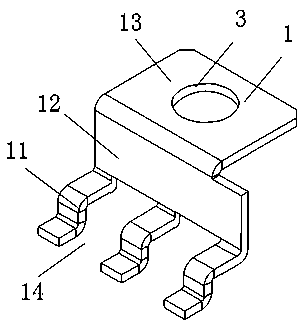
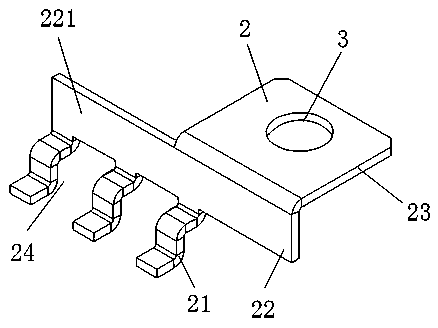
[0030] In order to reduce the parasitic inductance of the lead terminals, it is common practice to reduce the distance between the terminals as Figure 6 As shown, it consists of a pair of parallel and coplanar power terminals 1'' and 2'' with small spacing, but this has a limited effect...


PUM


Abstract

The invention discloses a power module low-inductance lead terminal. The lead terminal comprises a first lead terminal body and a second lead terminal body which are connected with a positive busbar and a negative busbar of an external power source of a power module. The first lead terminal body comprises a plurality of first lead terminal pins, first supporting parts and first fixed connecting parts which are connected sequentially. The second lead terminal body comprises a plurality of second lead terminal pins, second supporting parts and second fixed connecting parts which are connected sequentially. The first lead terminal pins of the first lead terminal body and the second lead terminal pins of the second lead terminal body are arranged in a staggered mode. The pins of the two terminal bodies are located on the same straight line so as to reduce terminal parasitic inductance, and correspondingly, copper foil on the DBC is designed to be in a staggering shape, so that interconnection is achieved; the parallel crossing structure is adopted in the positive and negative terminal bodies, the loop area of the power lead terminal is reduced, and parasitic inductance of the power terminal bodies is greatly reduced, is about 11.9 nH, and is only half of that of a general power lead terminal; meanwhile, the occupied distance of the two lead terminal bodies on the power module is saved.

Description

technical field [0001] The invention relates to the technical field of low-inductance leads of power modules, in particular to low-inductance lead terminals of power modules. Background technique [0002] When designing the power module, in order to make the power module meet the working conditions of high current and high frequency, the parasitic inductance of the lead terminal of the power module should be reduced as much as possible to reduce the voltage fluctuation of the power terminal when it is turned on and off. [0003] The parasitic inductance of the module can be divided into lead terminal parasitic inductance L1, bonding wire parasitic inductance and L2, DBC distributed parasitic inductance L3, and the mutual inductance between the three. When the power module is turned on or off, the current suddenly rises and falls, due to Due to the existence of parasitic inductance, an induced voltage VL will be generated on the positive and negative lead terminals of the mod...

Claims


Application Information

Patent Timeline
Patent Type & Authority Applications(China)
IPC IPC(8): H01L23/485
CPCH01L23/485H01L23/4855
Inventor 庄伟东姚二现
Owner 南京银茂微电子制造有限公司
Why Eureka
Try Eureka