Inverter switching signal frequency conversion modulation method and opwm inverter

A frequency conversion modulation and switching signal technology, which is applied in the direction of converting AC power input into DC power output, output power conversion devices, electrical components, etc., can solve the problem of not giving, quantitative design maximum frequency deviation

Active Publication Date: 2017-12-22
JILIN UNIV +2
View PDF5 Cites 0 Cited by
  • Summary
  • Abstract
  • Description
  • Claims
  • Application Information

AI Technical Summary

Problems solved by technology

However, its research mainly focuses on the composition of the composite signal and the effect of the maximum frequency deviation of the composite signal on harmonic peak suppression, and does not give how to quantitatively design the maximum frequency deviation according to the required spectrum distribution and how to choose two periodic signals

Method used


Image

  • Inverter switching signal frequency conversion modulation method and opwm inverter
  • Inverter switching signal frequency conversion modulation method and opwm inverter
  • Inverter switching signal frequency conversion modulation method and opwm inverter

Examples


Embodiment Construction

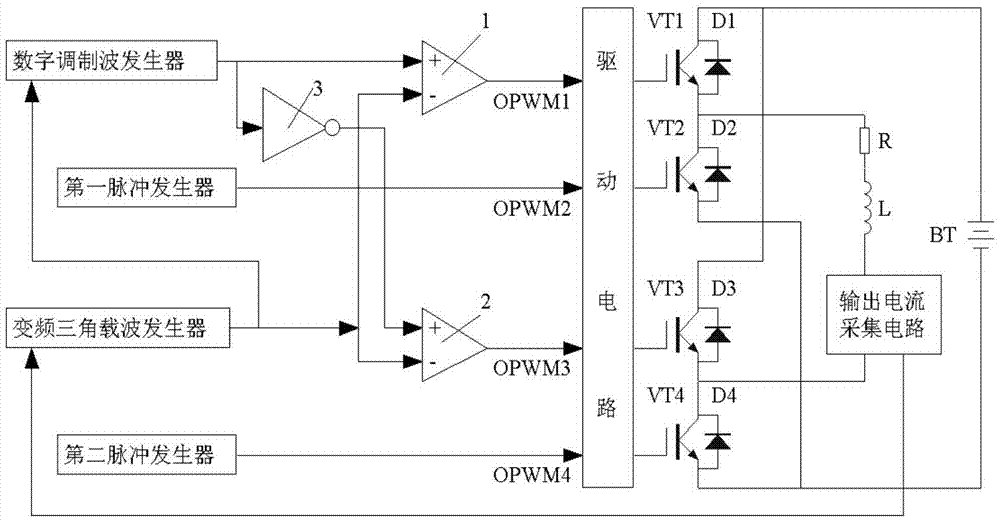
[0038] Such as figure 1 As shown, the OPWM inverter of the present invention includes a drive circuit, an H bridge, and the output of the drive circuit is connected to the input of the H bridge; device, the second pulse generator, the first comparator 1, the second comparator 2, the inverter 3, the control circuit that the output current acquisition circuit forms; The output of the digital modulation wave generator is connected to the first comparator 1 The noninverting input terminal and the input terminal of the inverter 3, the output terminal of the inverter 3 is connected to the noninverting input terminal of the second comparator 2; the output of the frequency conversion triangular carrier wave generator is respectively connected to the digital modulation wave generator and the first comparator 1, the inverting input terminal of the second comparator 2; the output of the first comparator 1, the second comparator 2, the first pulse generator, and the second pulse generator...


PUM


Abstract

The invention relates to a variable frequency modulation method for an inverter switching signal. The method comprises the following steps: calculating a peak value of a variable frequency triangular carrier at each frequency value according to a modulation signal, and generating the variable frequency triangular carrier accordingly, calculating a corresponding instantaneous value of a digital modulation wave at each frequency value of the variable frequency triangular carrier according to an analog modulation wave and the peak value of the variable frequency triangular carrier, and generating the digital modulation wave accordingly; comparing the digital modulation wave with the variable frequency triangular carrier to generate a first switch control signal, negating the digital modulation wave, and comparing the negated digital modulation wave with a voltage value of the variable frequency triangular carrier to generate a second switch control signal; inputting the first and second switch control signals and first and second pulse signals to a driving circuit, controlling the on-off of an H bridge switching tube, and obtaining positive and negative current signals at both ends of a load; and repeating the above steps to obtain alternating current signals at both ends of the load. The variable frequency modulation method provided by the invention is used for inhibiting the electromagnetic interference of the output current signal of the inverter, so that the output current signal is closer to an ideal signal.

Description

technical field [0001] The invention relates to an electrical detection instrument in geophysical detection, in particular to an inverter switching signal frequency conversion modulation method and an OPWM inverter suitable for a time-domain electromagnetic transmitting circuit. Background technique [0002] The switching signal of the traditional PWM inverter is generated by comparing the fixed-frequency triangular carrier wave with the modulation wave, that is, the inverter works at a fixed carrier frequency. After being applied to the transmitter, the output current of the transmitter contains a phenomenon of large-amplitude harmonics. It will not only cause electromagnetic interference, but also increase the switching loss of the bridge power device, which has a certain gap with the ideal output current signal. In addition, some large-amplitude intermediate-frequency harmonic components in the current are likely to cause mechanical resonance and reduce system stability. ...

Claims


Application Information

Patent Timeline
Patent Type & Authority Patents(China)
IPC IPC(8): H02M7/5395H02M7/5387H02M1/12H02M1/44
CPCH02M1/12H02M1/44H02M7/53873H02M7/5395
Inventor 于生宝高丽辉陈楠黄勇李齐刘伟宇
Owner JILIN UNIV
Why Eureka
Try Eureka