Motor control device, compressor, air conditioner and program

A technology for a control device and a motor, which is applied in the direction of motor generator control, electronic commutation motor control, and control of electromechanical transmission devices, etc., can solve problems such as no special records, and achieve the effect of reducing noise or vibration

Active Publication Date: 2016-04-27
HITACHI APPLIANCES INC
View PDF4 Cites 25 Cited by
  • Summary
  • Abstract
  • Description
  • Claims
  • Application Information

AI Technical Summary

Problems solved by technology

[0003] However, the control device for the electric motor connected to the compressor in Patent Document 1 does not specifically describe that it is not based on the normalized torque mode.
In addition, there is no particular description that there is a timing difference between the estimated position of the motor stator and the voltage application phase due to the restriction of the response frequency of the motor control device.

Method used


Image

  • Motor control device, compressor, air conditioner and program
  • Motor control device, compressor, air conditioner and program
  • Motor control device, compressor, air conditioner and program

Examples


no. 1 Embodiment approach

[0136]

[0137] 〔the whole frame〕

[0138] Next, refer to Figure 11 , the configuration of the first embodiment of the present invention will be described.

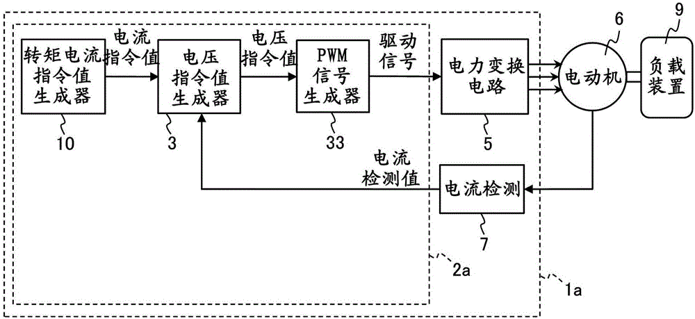
[0139] In this embodiment, if Figure 11 Shown, instead of Comparative Example 1 (see figure 1 ) In the motor control device 1a, the motor control device 1b is applied. The difference between the motor control devices 1a and 1b is that a control unit 2b is applied instead of the control unit 2a. A ripple torque estimator 16, a ripple torque current command value generator 11f, and an adder 90a are added to the control unit 2b. here, Figure 12 The details of the control unit 2b of this embodiment are shown.

[0140] (pulsating torque estimator 16)

[0141] Next, the ripple torque estimator 16 will be described, but first refer to Figure 13 (a), Figure 13 (b) The principle of the ripple torque estimator 16 will be described. Figure 13 (a) is used to illustrate the torque τ through the motor m and load torq...

no. 2 Embodiment approach

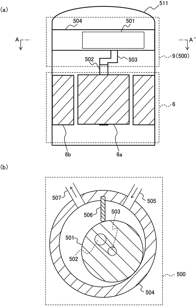
[0174] Next, refer to Figure 17 , the configuration of the compressor 302 according to the second embodiment of the present invention will be described. In addition, the same code|symbol is attached|subjected to the component corresponding to the component shown in the comparative example 1 already demonstrated and 1st Embodiment, and description is abbreviate|omitted.

[0175] In the compressor 302, the electric motor 6 and the compression mechanism part 500 which are power sources are attached in the airtight container 511. As shown in FIG. Furthermore, the motor 6 is connected to the motor control device 301 via a distribution cable 310 . Furthermore, a shaft 502 coupled to the rotor 6 a of the electric motor 6 and a rotor piston 501 are connected via a crankshaft 503 . Accordingly, the rotor piston 501 rotates eccentrically in accordance with the rotation of the motor 6, and a series of processes such as suction, compression, and discharge are executed. The suction pip...

no. 3 Embodiment approach

[0179]

[0180] Next, refer to Figure 18 An air conditioner according to a third embodiment of the present invention will be described. exist Figure 18 Among them, the air conditioner 300 has an indoor unit 303, an outdoor unit 304, and a pipe 305 connecting them. The indoor unit 303 is provided with an indoor heat exchanger 306 and a blower 307 for blowing air to the indoor heat exchanger 306 . In addition, the outdoor unit 304 is provided with a compressor 302 and a motor control device 311 for controlling the compressor 302 , and both are connected via a distribution cable 310 . Furthermore, the outdoor unit 304 is provided with an outdoor heat exchanger 308 and a blower 309 for blowing air to the outdoor heat exchanger 308 . When cooling the room, the refrigerant is supplied from the outdoor heat exchanger 308 of the outdoor unit 304 to the indoor heat exchanger 306 of the indoor unit 303 via the upper pipe 305 in the drawing. The vaporized refrigerant after coolin...


PUM


Abstract

The invention provides a motor control device, a compressor, an air conditioner and a program. In a motor control device applied in an air conditioner and the like, restriction on response frequency of the motor control device can be compensated and noise or vibration of a motor can be reduced. The motor control device is provided with an electric power conversion circuit and a control part. The electric power conversion circuit converts direct-current voltage into alternating-current voltage and drives a motor connected with a load device via the alternating-current voltage. The control part outputs a driving signal used for driving the electric power conversion circuit, presumes a rotation angle position (a shaft error delta theta c) of the motor and changes the duty ratio of the driving signal according to a presumed or preset load changing mode (differential torque presumed value delta tm^) and the rotation angle position (shaft error delta theta c).

Description

technical field [0001] The present invention relates to a motor control device, a compressor, an air conditioner and a program. Background technique [0002] As a background technology of a motor control device applied to an air conditioner or the like, for example, claim 1 of Patent Document 1 states that "a torque control unit that generates torque for controlling the motor according to the rotational position of the motor output torque fluctuation compensation torque mode, and correct the current value supplied to the motor”. [0003] However, the control device for the electric motor connected to the compressor in Patent Document 1 does not particularly describe that it does not presuppose the normalized torque mode. In addition, there is no particular description that there is a timing difference between the estimated position of the motor stator and the voltage application phase due to the restriction of the response frequency of the motor control device. [0004] Pa...

Claims


Application Information

Patent Timeline
Patent Type & Authority Applications(China)
IPC IPC(8): H02P21/05F24F1/00F04D25/06
Inventor 铃木尚礼田村建司
Owner HITACHI APPLIANCES INC
Why Eureka
Try Eureka