Time-difference generator using two-pole balance

A time difference and generator technology, applied to synchronous motors with stationary armatures and rotating magnets, electrical components, electromechanical devices, etc., can solve generator damage, generator fire damage, instrument and equipment damage, etc. problems, to achieve the effect of improving power generation efficiency, improving commerciality and reliability, and increasing power generation capacity

Active Publication Date: 2018-01-02
李禹宗
View PDF10 Cites 0 Cited by
  • Summary
  • Abstract
  • Description
  • Claims
  • Application Information

AI Technical Summary

Problems solved by technology

[0008] On the other hand, if we look at the process of generating electricity between the magnet and the iron core in the conventional generator, it can be found that due to the occurrence of hysteresis loss due to reverse current and eddy current due to magnetic motion, meaningless heavy loads, and generate heat
[0009] In particular, if excessive current is used and if an accidental short circuit (short circuit) occurs, there is a problem that various instruments and equipment will be damaged due to fire damage to the generator or power failure due to overload
[0010] Moreover, due to the hidden danger of damage to the generator, it is absolutely impossible to make the power consumption reach 100% of the total power actually produced, or to use close to the full amount of power output at the risk of overload

Method used


Image

  • Time-difference generator using two-pole balance
  • Time-difference generator using two-pole balance
  • Time-difference generator using two-pole balance

Examples


Embodiment Construction

[0047] Hereinafter, preferred embodiments of the present invention will be described in detail with reference to the accompanying drawings.

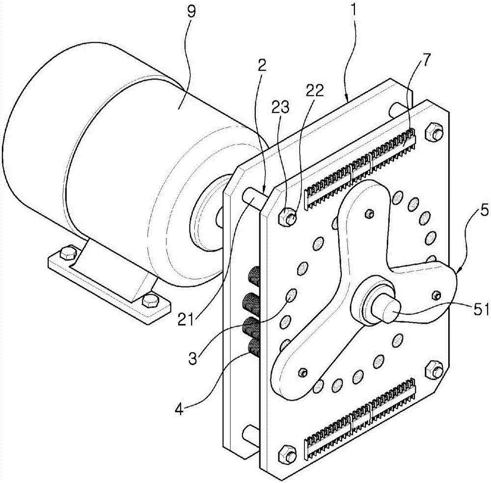
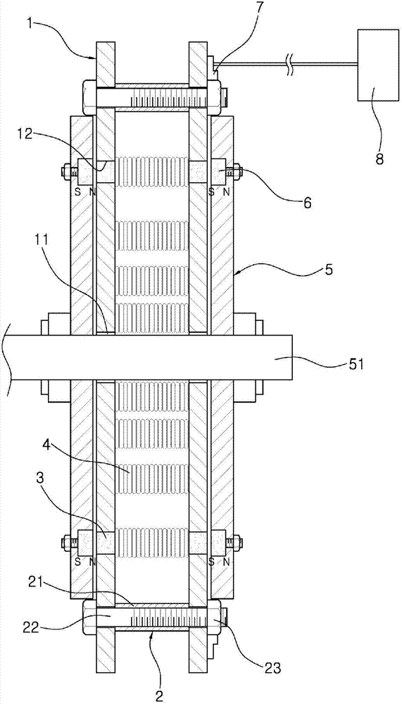
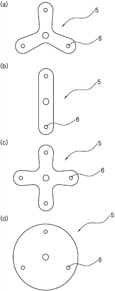
[0048] figure 1 is a perspective view of a generator according to an embodiment of the present invention, figure 2 is a sectional view of a generator according to an embodiment of the present invention, image 3 Parts (a) to (d) are front views showing various embodiments of the rotating plate for a rotor in the present invention, Figure 4 It is the front view of the fixed plate of the generator of another embodiment of the present invention, Figure 5 Parts (a) and (b) of (a) are exemplary front views of rotating plates for a plurality of rotors applied to another embodiment of the present invention.

[0049] Accordingly, the time-difference generator using two-pole balance of the present invention is characterized in that it includes: a pair of fixed plates 1, forming a rotating shaft passing hole 11 at the center point, and leavi...


PUM


Abstract

The present invention relates to a time-difference generator utilizing two-pole balance. In particular, the above-mentioned time-difference generator utilizing two-pole balance is characterized in that it comprises: a pair of fixing plates forming a rotation shaft passing hole at a central point, and extending along a circumference having a prescribed diameter. A plurality of ferrite core fixing holes are formed; a plurality of ferrite cores are fixedly installed on a pair of fixing plates in such a shape that both ends of each ferrite core are respectively inserted into the above-mentioned ferrite core fixing holes between them, so that the magnetic field forms a closed loop; a plurality of winding coils are arranged in the shape of winding on the outer peripheral surface of the above-mentioned ferrite core at a predetermined rotational speed; The above-mentioned pair of fixing plates are respectively fixed to both ends of the rotating shaft in the state of being arranged on the outer side of the pair of fixing plates. and a plurality of permanent magnets are formed inside the rotating plate for the rotor in such a shape that the south pole and the north pole have opposite directions, and are fixedly arranged so as to be arranged at predetermined intervals. Therefore, not only the power generation efficiency of the generator itself can be greatly improved, but also the power generation capacity can be greatly increased, so that the commerciality and reliability of the generator itself can be greatly improved.

Description

technical field [0001] The present invention relates to a time-difference generator using two-pole balance. More specifically, the invention is made in such a manner that a pair of fixed plates arranged in parallel with a predetermined distance are arranged at a predetermined interval. A plurality of ferrite cores wound with winding coils are fixedly installed, a rotating plate for the rotor is installed outside the pair of fixed plates, and a pair or more of permanent magnets are fixedly installed on the rotor in such a manner that they are arranged at predetermined intervals. Using a rotating plate, the rotating shaft fixed at the center point of the above-mentioned rotating plate for the rotor is connected to the shaft of the rotating force generating unit so that the winding coils respectively wound on a plurality of ferrite cores leave mutually different The voltages are generated independently by means of the same time difference (ie, independent generators). Backgroun...

Claims


Application Information

Patent Timeline
Patent Type & Authority Patents(China)
IPC IPC(8): H02K21/24H02K21/12
CPCH02K21/24H02K1/182H02K1/2796H02K1/02H02K1/14
Inventor 安钟石
Owner 李禹宗
Why Eureka
Try Eureka