Waste gas adsorption treatment device and treatment method

A technology of adsorption treatment and treatment method, which is applied in the field of waste gas adsorption treatment devices, can solve problems such as personal safety and property safety threats, combustion or explosion accidents of waste gas adsorption treatment devices, etc., achieves strong fire and explosion protection performance, reduces explosion accidents, and reduces hazards Effect

Active Publication Date: 2018-05-11
AEROSPACE KAITIAN ENVIRONMENTAL TECH CO LTD
View PDF8 Cites 0 Cited by
  • Summary
  • Abstract
  • Description
  • Claims
  • Application Information

AI Technical Summary

Problems solved by technology

Since acetone is a flammable gas, the above-mentioned treatment process is easy to cause combustion or explosion accidents of the waste gas adsorption treatment device, which poses a great threat to personal safety and property safety.

Method used


Image

  • Waste gas adsorption treatment device and treatment method
  • Waste gas adsorption treatment device and treatment method
  • Waste gas adsorption treatment device and treatment method

Examples


Embodiment 1

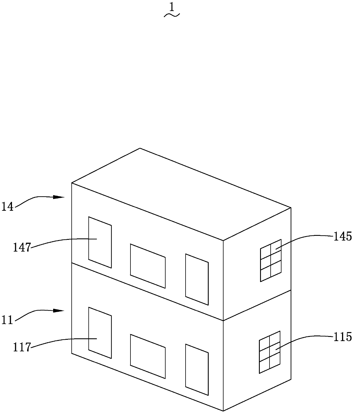
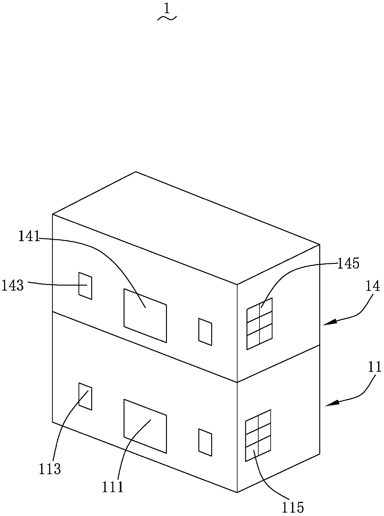
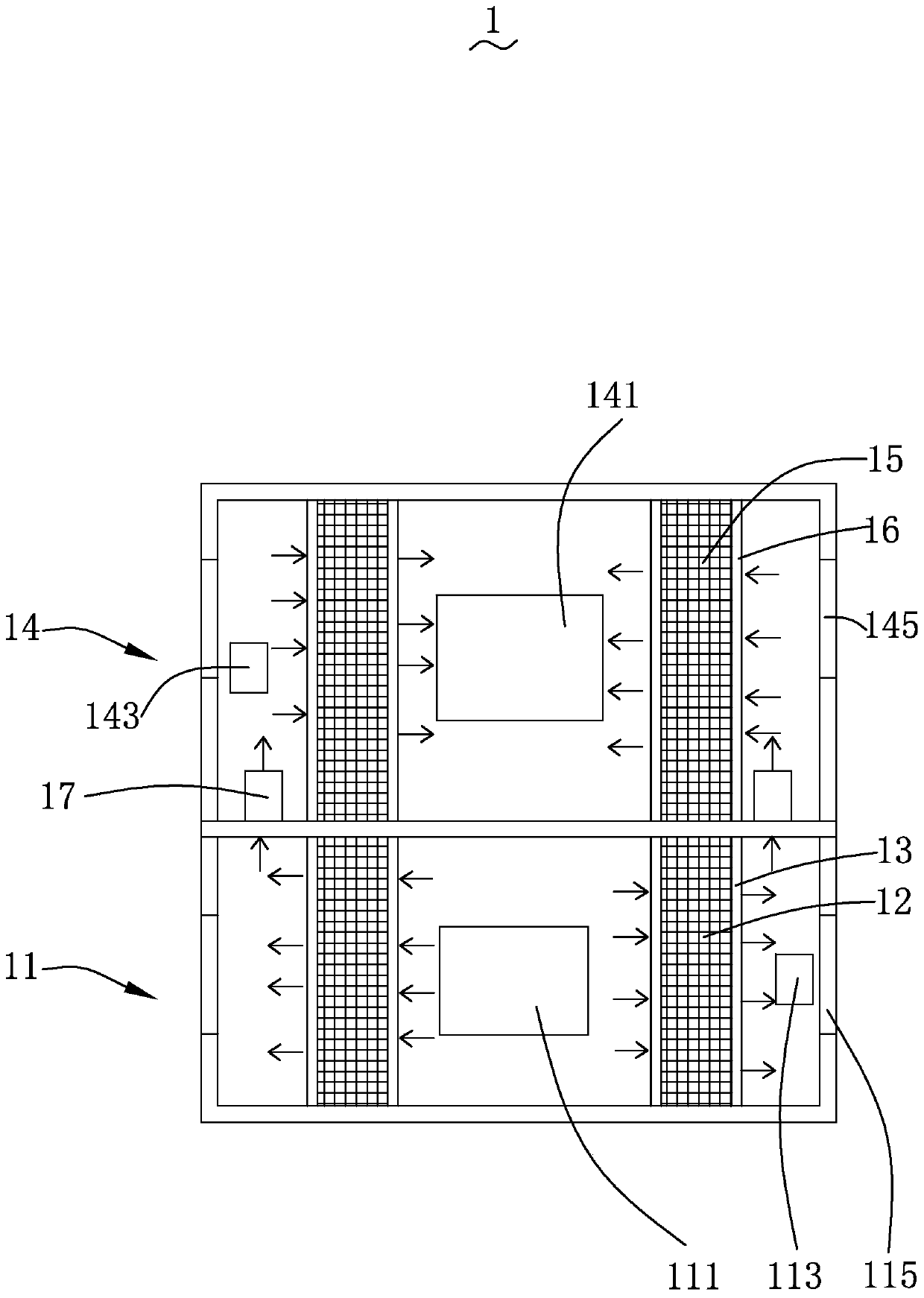
[0031] Please refer to Figure 1 to Figure 3 ,in figure 1 It is a schematic diagram of the three-dimensional structure of Embodiment 1 of the exhaust gas adsorption treatment device of the present invention; figure 2 It is a schematic three-dimensional structure diagram from another angle of Embodiment 1 of the exhaust gas adsorption treatment device of the present invention; image 3 It is a schematic diagram of gas flow in the adsorption process of Embodiment 1 of the exhaust gas adsorption treatment device of the present invention. The exhaust gas treatment device 1 includes a first adsorption box 11 , a primary flame retardant adsorber 12 , a primary support 13 , a second adsorption box 14 , a secondary flame retardant adsorber 15 , a secondary support 16 and a connecting pipe 17 .

[0032] The first adsorption box 11 and the second adsorption box 14 are stacked, and the first adsorption box 11 is located below the second adsorption box 14, and the first adsorption box ...

Embodiment 2

[0064] Please refer again Figure 6 to Figure 8 ,in Figure 6 It is a schematic diagram of the three-dimensional structure of Embodiment 2 of the exhaust gas adsorption treatment device of the present invention, Figure 7 It is a schematic diagram of the three-dimensional structure of another angle of Embodiment 2 of the exhaust gas adsorption treatment device of the present invention, Figure 8 It is a schematic diagram of gas flow in the adsorption process of Embodiment 2 of the exhaust gas adsorption treatment device of the present invention. The exhaust gas adsorption treatment device 2 includes a first adsorption box 21, a primary flame retardant adsorber 22, a primary support 23, a second adsorption box 24, a secondary flame retardant adsorber 25, a secondary support 26, a connecting pipe 27 and Electric damper 28.

[0065] Except that the number of the first desorption port 213 and the second desorption port 243 are different, and the electric air valve 28 is added, ...


PUM


Abstract

The invention provides an exhaust gas adsorption treatment device. The exhaust gas adsorption treatment device includes a first adsorption box, a second adsorption box, a connecting pipe connecting the first adsorption box and the second adsorption box, a primary flame-retardant adsorber, and a secondary flame-retardant adsorber. The second adsorption box is stacked on the first adsorption box, the first adsorption box includes a first ventilation opening and a first desorption opening opened on its side wall, and the second adsorption box includes a The second ventilation port and the second desorption port of the wall, the first-stage flame-retardant adsorber is arranged in the first adsorption box, and the second-stage flame-retardant adsorber is arranged in the second adsorption box, so The first vent, the first-stage flame-retardant adsorber, the communication pipe, the second-stage flame-retardant adsorber, and the second vent are sequentially connected to form an air passage. The present invention also provides a treatment method based on the waste gas adsorption treatment device. Compared with related technologies, the exhaust gas adsorption treatment device of the present invention saves space and can reduce the hazards of explosion accidents.

Description

technical field [0001] The invention relates to the field of waste gas treatment, in particular to a waste gas adsorption treatment device and treatment method. Background technique [0002] A large amount of organic waste gas is often generated during the spraying process. In the traditional spraying process, the organic waste gas generated is often directly discharged to the atmosphere, and the direct discharge of organic waste gas causes dust and toxic substances to enter the atmosphere directly, which is harmful to human health and the ecological environment. have had adverse effects. [0003] Due to the large amount of organic waste gas to be treated, a large-scale waste gas adsorption treatment device is used in the related art to perform multi-stage adsorption treatment on the organic waste gas. The waste gas adsorption treatment device occupies a large area and wastes space. The main component of the organic waste gas is acetone. In order to treat the acetone in the...

Claims


Application Information

Patent Timeline
Patent Type & Authority Patents(China)
IPC IPC(8): B01D53/04B01D46/00
CPCB01D53/04B01D2267/30B01D46/62
Inventor 刘伟胡胜刘华
Owner AEROSPACE KAITIAN ENVIRONMENTAL TECH CO LTD
Why Eureka
Try Eureka