Ceramic discs for food grinding
A technology of grinding and ceramics, applied in the fields of application, food science, cocoa, etc., can solve the problems of poor impact resistance and high brittleness of ceramics, and achieve the effects of not being easy to wear, overcoming poor impact resistance, and improving service life
- Summary
- Abstract
- Description
- Claims
- Application Information
AI Technical Summary
Problems solved by technology
Method used
Image
Examples
specific Embodiment approach 1
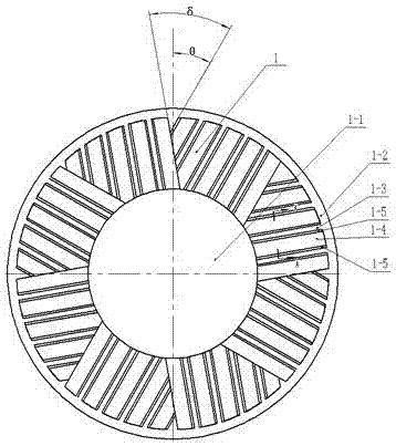
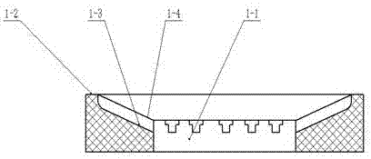
[0048] Such as figure 1 , figure 2 with image 3 As shown, the substrate of the static grinding disc 1 of the present invention is a cylinder with a thickness of 15 mm to 35 mm and an outer diameter of 60 mm to 500 mm, but not limited to 500 mm. The center of the static grinding disc 1 is provided with a feed hole 1-1, and the feed hole 1 The diameter of -1 is 20-80mm, so that the material can be fed from the central feeding port of the static grinding disc 1, and the food material can be diffused to the surroundings, which overcomes the problem that the eccentric feeding port feeds unevenly in one direction, and the food material cannot enter the center of the grinding disc. According to different food materials and different purposes, different static grinding disc thicknesses, static grinding disc outer diameters and static grinding disc feeding hole diameters can also be selected. The working surface of the static grinding disc 1 is provided with a 3-10mm wide gap along...
specific Embodiment approach 2
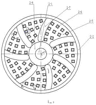
[0049] Such as Figure 4 , Figure 5 , Image 6 with Figure 7 As shown, the base body of the movable grinding disc 2 of the present invention is a cylinder with a thickness of 15 mm to 35 mm and an outer diameter of 60 mm to 500 mm, but not limited to 500 mm. The center of the movable grinding disc 2 is provided with a motor shaft mounting hole 2-1 and a fixed nut installation Plane 2-8, the diameter of the mounting hole 2-1 matches the diameter of the output shaft of the motor used for its installation, the back of the moving grinding disc 2 is a light plane 2-3, and a weight-reducing groove is arranged on the light plane 2-3 2-4, the working face of the movable grinding disc 2 is provided with a peripheral grinding plane 2-2 of 3-10mm wide along the outer diameter circumference, and the peripheral grinding plane 2-2 of the dynamic grinding disc and the installation hole 2-1 are The concave plane 2-5 is provided with a material guide groove 2-7 and a trapezoidal tooth 2-6...
specific Embodiment approach 3
[0050] Such as Figure 8 As shown, the present invention comprises a static grinding disc 1 and a moving grinding disc 2, the substrate of the static grinding disc 1 is a cylinder, and the center of the static grinding disc 1 is provided with a feeding hole 1-1, and the working surface of the static grinding disc 1 is along the circumference of the outer diameter A peripheral grinding plane 1-2 is arranged inwardly of the static grinding disc, and the inner diameter of the peripheral grinding plane 1-2 of the static grinding disc and the feeding hole 1-1 is a concave conical surface 1-3, and the base body of the moving grinding disc 2 is a cylinder , a motor shaft mounting hole 2-1 is provided at the center of the movable millstone 2, and the working surface of the movable millstone 2 is provided with a peripheral grinding plane 2-2 along the outer diameter circumference of the movable millstone. Between the holes 2-1 is a concave plane 2-5, and helical teeth 1-4 are provided ...
PUM
| Property | Measurement | Unit |
|---|---|---|
| thickness | aaaaa | aaaaa |
| diameter | aaaaa | aaaaa |
| width | aaaaa | aaaaa |
Abstract
Description
Claims
Application Information
 - R&D
- Intellectual Property
- Life Sciences
- Materials
- Tech Scout
- Unparalleled Data Quality
- Higher Quality Content
- 60% Fewer Hallucinations
Browse by: Latest US Patents, China's latest patents, Technical Efficacy Thesaurus, Application Domain, Technology Topic, Popular Technical Reports.
© 2025 PatSnap. All rights reserved.Legal|Privacy policy|Modern Slavery Act Transparency Statement|Sitemap|About US| Contact US: help@patsnap.com


