
Medical water supplier

A water supply machine and concentrated water technology, which is applied in multi-stage water treatment, water/sewage treatment, non-polluted water treatment, etc.

Inactive Publication Date: 2016-05-04
朱湘陵
View PDF2 Cites 1 Cited by
  • Summary
  • Abstract
  • Description
  • Claims
  • Application Information

AI Technical Summary

Problems solved by technology

[0002] In view of the general water supply machine industry generally adopts compressor refrigeration, the equipment is large in size, takes up too much space, produces too much noise during work, and requires the use of refrigerants, which pollutes the environment
[0003] There are also electronic refrigeration, and the common electronic refrigeration technology has the following problems: 1. In terms of performance: the cooling water capacity is poor, far inferior to compression refrigeration, and it is difficult to meet people's daily needs for drinking cold water; 2. Technical aspect: the heat dissipation technology is backward , leading to the long-term low-efficiency cooling conditions of semiconductor refrigeration chips; 3. In terms of hygiene: the closed structure of the gallbladder cavity of the cooler cannot be cleaned, and it is easy to cause secondary pollution of water quality, which cannot meet the requirements of medical water supply; 4. In terms of energy saving: existing The water supply machine of the technology passes through the temperature sensing device, and the cold water will continue to cool after it becomes hot. When the frequency of use is not high, such as at night, the energy consumption is very high
[0004] Therefore, ordinary water supply machines cannot meet the requirements of medical water supply, and continuous innovation is still needed

Method used


Image

  • Medical water supplier
  • Medical water supplier
  • Medical water supplier

Examples


Embodiment Construction

[0022] The present invention will be described in further detail below in conjunction with the accompanying drawings.

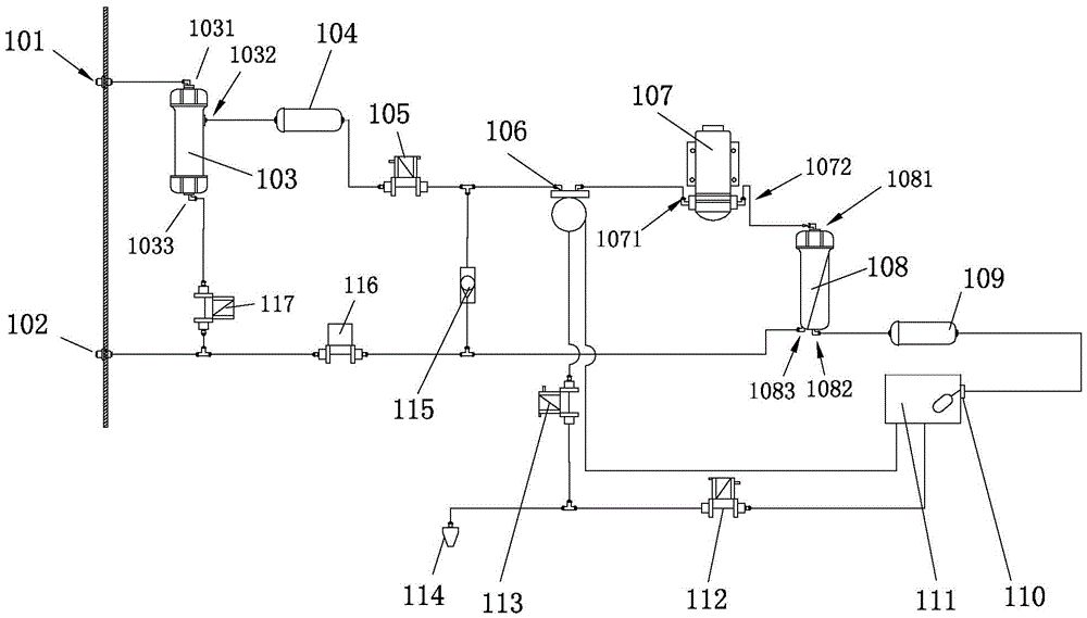
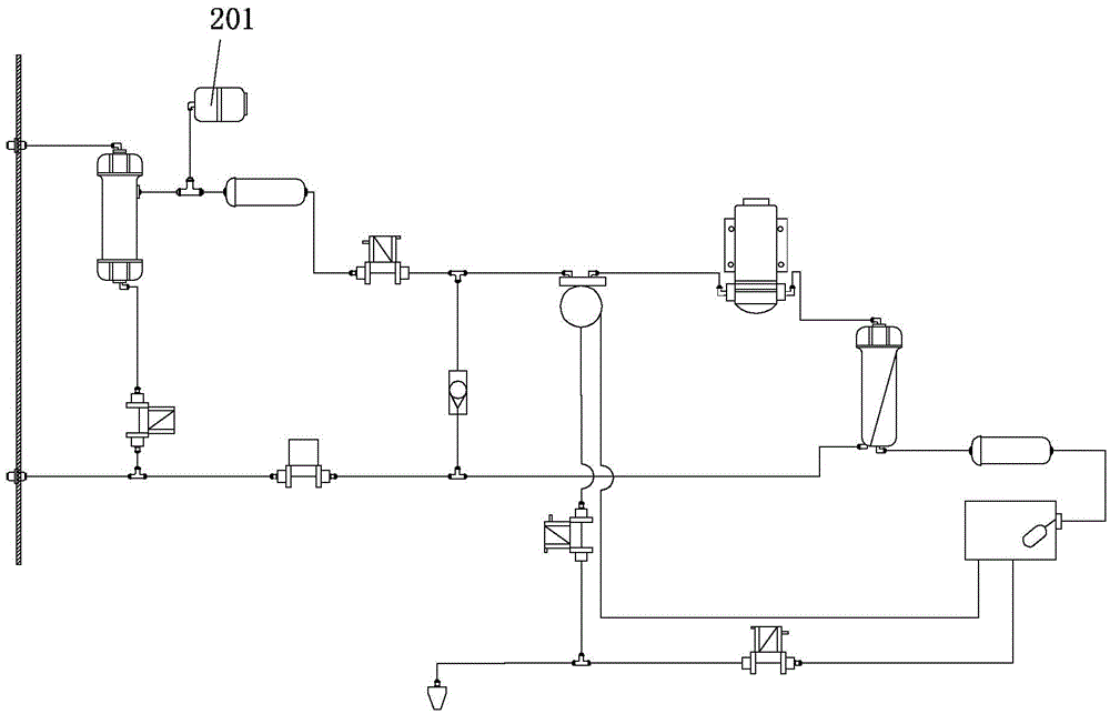
[0023] The first embodiment of the present invention is an energy-saving, hygienic fluorine-free and environmental-friendly medical water supply machine with electronic refrigeration, refer to figure 1 , figure 2 , the medical water supply machine includes a water inlet 101, a pure water inlet 114, and a filter device arranged between the water inlet 101 and the water outlet 102 includes a pre-treatment device 103 and 104, a refrigeration device 106, a reverse osmosis filter device 108, and a post-treatment filter device 109, automatic flushing devices 116 and 117 and concentrated water discharge port 102, pre-treatment devices 103 and 104 are arranged between water inlet 101 and refrigeration device 106, reverse osmosis filter device 108 is arranged between refrigeration device 106 and post-treatment filter Between 109, the automatic flushing device is arr...


PUM


Abstract

The invention relates to medical water treatment equipment, in particular to an energy-saving and sanitary medical water supplier with a rapid refrigeration function. The medical water supplier comprises a water inlet, a pure water outlet, a filtering device, an electronic refrigeration device and a booster bump, and further comprises a water draining control device, wherein the filtering device, the electronic refrigeration device and the booster bump are arranged between the water inlet and the pure water outlet; the electronic refrigeration device is arranged between the pure water outlet and a water tank, and comprises two sets of refrigeration equipment, namely an electronic refrigeration circuit and a circulating water cooling mechanism; the circulating water cooling mechanism is connected in series onto a water channel between post-treatment devices and the water inlet; the electronic refrigeration device has an open-type ice container; the ice container is vertically arranged under the water tank, thereby being convenient to disassemble and clean; the water draining control device comprises an electromagnetic valve I arranged between the electronic refrigeration device and the pure water outlet as well as an electromagnetic valve II arranged between the water tank and the pure water outlet. The medical water supplier provided by the invention has an electronic refrigeration function; and by adoption of the medical water supplier, water is protected from secondary pollution due to the ice container.

Description

technical field [0001] The invention relates to medical water treatment equipment, in particular to an energy-saving and hygienic medical water supply machine with rapid cooling function. Background technique [0002] In view of the general water supply machine industry generally adopts compressor refrigeration, the equipment is large in size, takes up too much space, produces too much noise during operation, and requires the use of refrigerants, which pollutes the environment. [0003] There are also electronic refrigeration, and the common electronic refrigeration technology has the following problems: 1. In terms of performance: the cooling water capacity is poor, far inferior to compression refrigeration, and it is difficult to meet people's daily needs for drinking cold water; 2. Technical aspect: the heat dissipation technology is backward , leading to the long-term low-efficiency cooling conditions of semiconductor refrigeration chips; 3. In terms of hygiene: the cl...

Claims


Application Information

Patent Timeline
Patent Type & Authority Applications(China)
IPC IPC(8): C02F9/06C02F103/04
CPCC02F9/00C02F1/441C02F1/444C02F1/46C02F2103/04C02F2209/02C02F2301/08
Inventor 朱湘陵
Owner 朱湘陵
Learn More