An integrated air compressor

An air compressor, integrated technology, applied in the direction of liquid variable capacity machinery, mechanical equipment, variable capacity pump components, etc., can solve problems such as large space occupation, complex structural design, and dangerous high-pressure pipelines, and achieve space utilization High efficiency, easy engineering support, high integration effect

Active Publication Date: 2017-09-01
四川空分设备(集团)有限责任公司
View PDF8 Cites 0 Cited by
  • Summary
  • Abstract
  • Description
  • Claims
  • Application Information

AI Technical Summary

Problems solved by technology

[0002] Traditional air compressors, especially high-pressure air compressors, have a complex overall structure design, take up a lot of space, and consume a lot of lubricating oil. In addition, the design method of fastening the host, cooler, and pipelines to the foundation is often used, so , there are many disadvantages when the volume of the compressor unit is small. For example, due to the easy over-positioning during installation, the requirements for matching the compressor unit with the foundation and casing are high. When the cylinder piston of the compressor compresses the gas, the generated The vibration is relatively large, and the vibration will be transmitted to the compressor body, cooler, and pipeline respectively, so that it is easy to crack at the place where the stress is concentrated, which is especially dangerous for high-pressure pipelines, and the noise of the compressor is relatively large when it is working. In addition, when the compressor unit fails, it is very cumbersome to judge the fault point, and it is difficult to accurately judge which stage of the cylinder and its pipeline are faulty.

Method used


Image

  • An integrated air compressor
  • An integrated air compressor
  • An integrated air compressor

Examples


Embodiment Construction

[0020] In order to make the object, technical solution and advantages of the present invention clearer, the present invention will be described in detail below in conjunction with the accompanying drawings and specific embodiments. It should be understood that the specific embodiments described here are only used to explain the present invention, not to limit the present invention.

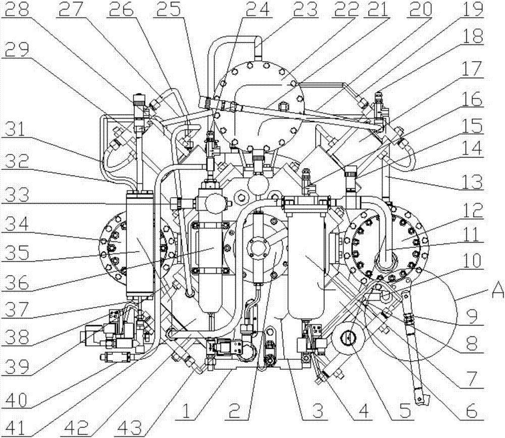
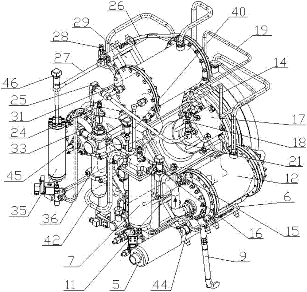
[0021] Such as figure 1 , image 3 , Figure 4 The shown integrated air compressor includes an integrated base 1, a fuselage 3, a cylinder and a gas cooler, wherein the cylinders specifically include a first-stage cylinder 6, a second-stage cylinder 41, a third-stage cylinder 29, and a fourth-stage cylinder 17. The gas cooler specifically includes a primary gas cooler 12, a secondary gas cooler 34, and a composite cooler 22 composed of a tertiary gas cooler and a quaternary gas cooler. The fuselage 3 is fixedly installed on the integrated foundation 1, and a lubricating oil pump 2 is installed ...


PUM


Abstract

The invention provides an integrated air compressor which comprises a machine body, a first-stage cylinder, a second-stage cylinder, a third-stage cylinder, a fourth-stage cylinder, a first-stage gas cooler, a second-stage gas cooler and a combined cooler. The first-stage cylinder, the second-stage cylinder, the third-stage cylinder and the fourth-stage cylinder are fixedly connected with the machine body and distributed in an X shape. The first-stage gas cooler, the second-stage gas cooler and the combined cooler are fixedly connected with the machine body, the first-stage gas cooler is arranged between the first-stage cylinder and the fourth-stage cylinder and in a neutral position, the second-stage gas cooler is arranged between the second-stage cylinder and the third-stage cylinder and in a neutral position, and the combined cooler is arranged between the third-stage cylinder and the fourth-stage cylinder and in a neutral position. The high-pressure gas leakage danger caused when pipelines (including gas paths and cooling water paths) between stages on the air compressor vibrate excessively and are pulled broken can be effectively avoided, and the integrated air compressor has the outstanding advantages of being high in integrity, high in space utilization rate, little in vibration, low in work noise and the like.

Description

technical field [0001] The invention relates to an air compressor, in particular to an integrated air compressor. Background technique [0002] Traditional air compressors, especially high-pressure air compressors, have a complex overall structure design, take up a lot of space, and consume a lot of lubricating oil. In addition, the design method of fastening the host, cooler, and pipelines to the foundation is often used, so , there are many disadvantages when the volume of the compressor unit is small. For example, due to the easy over-positioning during installation, the requirements for matching the compressor unit with the foundation and casing are high. When the cylinder piston of the compressor compresses the gas, the generated The vibration is relatively large, and the vibration will be transmitted to the compressor body, cooler, and pipeline respectively, so that it is easy to crack at the place where the stress is concentrated, which is especially dangerous for hig...

Claims


Application Information

Patent Timeline
Patent Type & Authority Patents(China)
IPC IPC(8): F04B27/02F04B39/06F04B39/16F04B39/10
CPCF04B27/02F04B39/06F04B39/10F04B39/16
Inventor 刘永为桂林肖佘家全王林江流朱云华王其雷刘树林
Owner 四川空分设备(集团)有限责任公司
Why Eureka
Try Eureka