
Quick heating system

A heating system and rapid heating technology, applied in electric heating systems, heating systems, household heating and other directions, can solve the problems of environmental damage, inability to deal with flue gas, and slow room temperature rise, so as to avoid temperature rise and improve heat dissipation. Speed, the effect of increasing the heating rate

Inactive Publication Date: 2016-05-04
钱连合
View PDF7 Cites 10 Cited by
  • Summary
  • Abstract
  • Description
  • Claims
  • Application Information

AI Technical Summary

Problems solved by technology

In the past, the common heating method was to use coal stoves for heating, and the heating in the house was often provided by boilers or heating stoves; with the improvement of environmental protection awareness and the deepening of the concept of sustainable development, the use of coal resources for heating has obviously It is no longer suitable for the development situation I live in, especially the family uses coal heating alone, and the flue gas cannot be treated, which will cause serious damage to the environment
Therefore, the way of using electricity for heating is becoming more and more popular. However, the existing heaters often use electric heating wires to heat the oil, and then use the oil to dissipate heat. The heating rate of the electric heating wires is very slow, resulting in an increase in room temperature. slow
At the same time, due to the high boiling point of oil, the temperature that the heater can reach is very high, which has a certain risk factor. When the heater reaches a high temperature, it will also cause uneven temperature distribution in the room and high local temperature. affect the comfort of the house

Method used


Image

  • Quick heating system
  • Quick heating system
  • Quick heating system

Examples


Embodiment 1

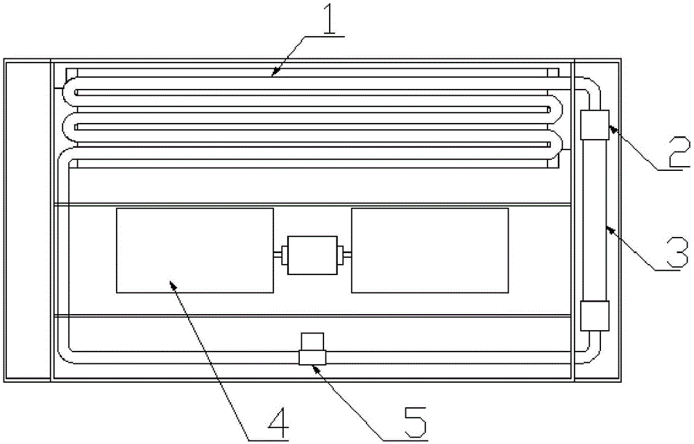
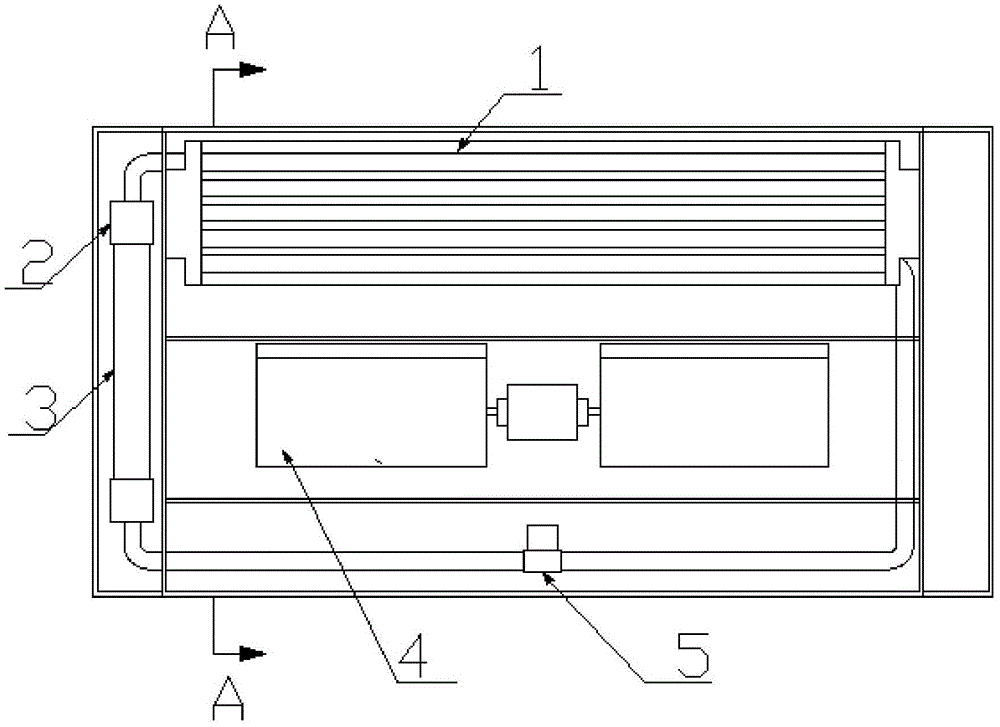
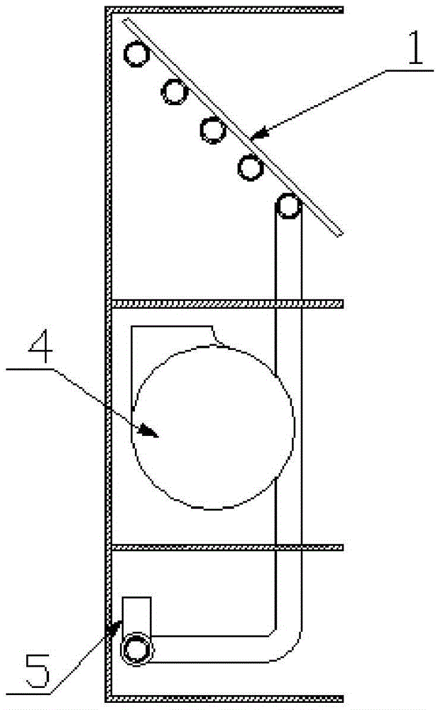
[0053] Such as Figure 1-3 As shown, the rapid heating heating system of this embodiment of the present invention includes a casing, and a heat dissipation circulation loop arranged inside the casing;

[0054] The housing is divided into three chambers horizontally, namely a heating chamber, a heat dissipation chamber and a control chamber. The heating chamber located in the middle is provided with a heat dissipation chamber, a fan chamber and a pump chamber in sequence from top to bottom; Heating device, the heating device includes at least one coated electric heating crystal tube 3 and upper and lower water collectors 2 arranged at both ends of the coated film electric heating crystal tube, the upper and lower water collectors 2 are respectively arranged There are an outlet water temperature sensor and a return water temperature sensor, the cooling fins 1 are placed horizontally in the heat dissipation chamber, the fan 4 is arranged corresponding to the cooling fins in the f...

Embodiment 2

[0057] On the basis of the above examples, if Figure 4-5 As shown, the heat dissipation cavity also includes an energy storage chamber, the energy storage chamber is arranged below the pump chamber, and the energy storage chamber is provided with a flexible accumulator 7 connected to the heat dissipation circulation circuit; the flexible energy storage chamber The device includes a rigid inner tube 9 and a flexible water bag 8 sleeved outside the rigid inner tube. A water storage cavity is arranged between the rigid inner tube 9 and the flexible water bag 8. Both ends of the flexible water bag 8 are connected to the The rigid inner tube 9 is sealed and connected, the tube wall of the rigid inner tube 9 is provided with a screen hole 10, and the inner wall of the energy storage chamber is provided with a limit switch 6 at a position corresponding to the flexible accumulator. When the water in the heat dissipation circulation loop expands, the flexible water bladder 8 expands, ...

Embodiment 3

[0061] On the basis of the above examples, if Figure 6-7 As shown, a piston accumulator can also be arranged in the accumulator chamber, and the piston accumulator includes a cylinder body 12 and a piston 13. A travel switch 14 is arranged at a position corresponding to the piston 13 in the energy storage chamber. When the water in the circulation circuit expands, the piston 13 moves to the open end of the cylinder body 12, triggers the travel switch 14, and the heating device stops heating. When the water in the heat dissipation circulation circuit is lost, the piston 13 13 moves to the end where the cylinder body 12 is connected with the circulation loop, and replenishes water in the circulation loop;

[0062] In this embodiment, a rigid cylinder body 12 and a piston 13 are used as accumulators, which are easy to install and reliable in performance. In addition, in the initial state, the piston 13 is located in the middle of the cylinder body 12. Since the water in the cir...


PUM


Abstract

The invention discloses a quick heating system and mainly aims at solving the problem that the quick heating system of the prior art has low heating speed as heating wires are adopted for heating. According to the technical scheme put forward by the invention, the quick heating system comprises a shell, a circulation loop arranged inside the shell, a draught fan and a control device for controlling the circulation loop and the draught fan, wherein the circulation loop comprises a loop pipeline as well as a heating device, cooling fins and a circulating pump which are connected to the pipeline; the heating device is vertically arranged in a heating cavity and comprises at least one film coated electrical heating crystal pipe, and upper and lower water collecting devices which are arranged at two ends of the film coated electrical heating crystal pipe; an outlet water temperature sensor and a return water temperature sensor are respectively arranged in the upper and lower water collecting devices; a circulating medium in the circulation loop is water; and the draught fan is arranged below the cooling fins. The quick heating system has fast heating speed and heat dissipation speed and increases room temperature increasing speed.

Description

technical field [0001] The invention relates to a rapid heating heating system. Background technique [0002] In winter in northern my country, the weather is very cold, and heating equipment is often needed. In non-central heating areas, it is necessary to solve the problem of heating in the house. In the past, the common heating method was to use coal stoves for heating, and the heating in the house was often provided by boilers or heating stoves; with the improvement of environmental protection awareness and the deepening of the concept of sustainable development, it is obvious that the use of coal resources for heating It is no longer suitable for the development situation I have lived in, especially the family uses coal heating alone, and the flue gas cannot be treated, which will cause serious damage to the environment. Therefore, the way of using electricity for heating is becoming more and more popular. However, the existing heaters often use electric heating wires ...

Claims


Application Information

Patent Timeline
IPC IPC(8): F24D13/04F24D19/10
CPCF24D13/04F24D19/1096F24D2200/08
Inventor 钱连合
Owner 钱连合
Learn More