Rapid composite material image damage detection method based on infrared imaging

A technology of impact damage and composite materials, applied in the field of infrared thermal wave nondestructive testing, can solve the problems of small single detection area, low efficiency and high cost, and achieve the effect of fast detection speed and large detection area

Active Publication Date: 2016-05-04
TIANJIN JINHANG INST OF TECH PHYSICS
View PDF6 Cites 11 Cited by
  • Summary
  • Abstract
  • Description
  • Claims
  • Application Information

AI Technical Summary

Problems solved by technology

[0006] The technical problem to be solved in the present invention is: how to propose a rapid detection method for impact damage of composite materials based on infrared imaging to solve

Method used


Image

  • Rapid composite material image damage detection method based on infrared imaging
  • Rapid composite material image damage detection method based on infrared imaging
  • Rapid composite material image damage detection method based on infrared imaging

Examples


Embodiment 1

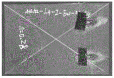
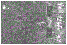
[0075] The composite material tested in this embodiment is a carbon fiber composite material, which has been impacted by an 8J drop hammer, and the damage position cannot be found from the front of the impact by visual inspection. Such as Figure 3-1 and Figure 3-2 A visible light image of the material to be inspected is shown.

[0076] Step 1: Build a detection system according to steps S1 and S2 of the technical solution, and perform necessary surface cleaning on the carbon fiber composite material to be tested. Since the surface of the material to be detected in this example is dark gray and has a high emissivity, there is no need to apply water-soluble black paint;

[0077] Step 2: Adjust the focal length of the thermal imaging camera so that the material to be inspected is clearly imaged on the thermal imaging camera, measure the distance from the material to be inspected to the rear end of the thermal imaging camera lens d=486mm, and the pixel size of the thermal imag...


PUM


Abstract

The invention belongs to the technical field of infrared heat wave nondestructive detection, and concretely relates to a rapid composite material image damage detection method based on infrared imaging. Compared with the prior art, the rapid composite material image damage detection method based on infrared imaging, using hot air as an excitation source, has the advantages of large one-time detection area, fast detection speed, no need of treatment of the surface finesse, and suitableness for onsite detection.

Description

technical field [0001] The invention belongs to the technical field of infrared thermal wave non-destructive detection, and in particular relates to a rapid detection method for impact damage of composite materials based on infrared imaging. Background technique [0002] Composite materials are composed of two or more materials with different properties, which are composed of materials with new properties in the macro (micro) through physical or chemical methods. Due to its high specific strength, high specific modulus, strong designability and low cost and many other excellent properties, it occupies an important position in the modern aerospace field. However, composite material structures are very prone to various damages caused by impacts during use and maintenance. For example, the collision of birds or stones during take-off and landing of the aircraft, the drop of wrenches during the maintenance process of workers, etc. Most impact damage surfaces are difficult to o...

Claims


Application Information

Patent Timeline
IPC IPC(8): G01N25/72
Inventor 李科钟安彪黄锐李玉杰马志强
Owner TIANJIN JINHANG INST OF TECH PHYSICS
Why Eureka
Try Eureka