Electromagnetic ultrasonic transducer of end portion-free detection blind area

A technology for detecting blind spots and ultrasonic waves, applied in the direction of using ultrasonic/sonic/infrasonic waves, using sound waves/ultrasonic/infrasonic waves to analyze solids, instruments, etc. Signal-to-noise ratio and other issues, achieve the effect of uniform distance, eliminate detection blind spots, increase strength and signal-to-noise ratio

Active Publication Date: 2016-05-04
SUZHOU PHASERISE TECH
View PDF13 Cites 10 Cited by
  • Summary
  • Abstract
  • Description
  • Claims
  • Application Information

AI Technical Summary

Problems solved by technology

[0003] The permanent magnets in the permanent magnet electromagnetic ultrasonic probes currently used all adopt a planar structure, and the effective contact surface on the steel pipe (rod) is small, and the direction of the magnetic force line is difficult to keep perpendicular to the surface of the tested object, resulting in obvious noise in the detection signal. and the signal-to-noise ratio is poor; and due to the limitation of the permanent magnet suction distribution, there are obvious detection blind spots, which cannot guarantee the complete detection of the DUT; and in order to ensure the signal-to-noise ratio and signal strength of the EMAT, the permanent magnet is usually as high as possible. The magnetic field strength of the magnet makes a strong adsorption force between the probe and the tested part, making it difficult to move relative to each other, and it is easy to cause damage to the surface of the workpiece during the moving or installation process; at the same time, the EMAT coil needs to be based on the detection function (guided wave, surface wave etc.) are often replaced, and are wearing parts, which need to be strictly protected

Method used


Image

  • Electromagnetic ultrasonic transducer of end portion-free detection blind area
  • Electromagnetic ultrasonic transducer of end portion-free detection blind area
  • Electromagnetic ultrasonic transducer of end portion-free detection blind area

Examples


Embodiment Construction

[0022] The present invention is described below in conjunction with accompanying drawing.

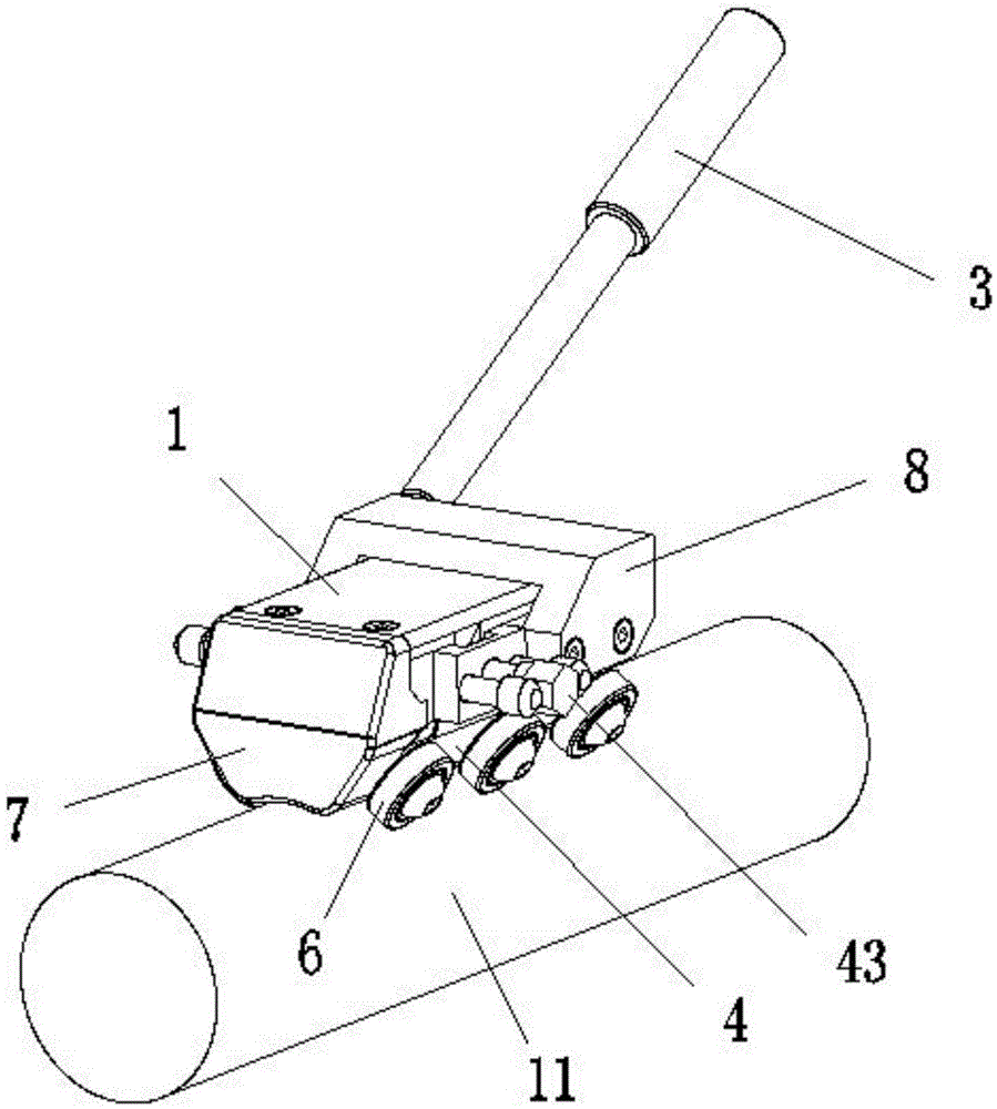
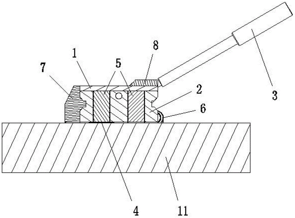
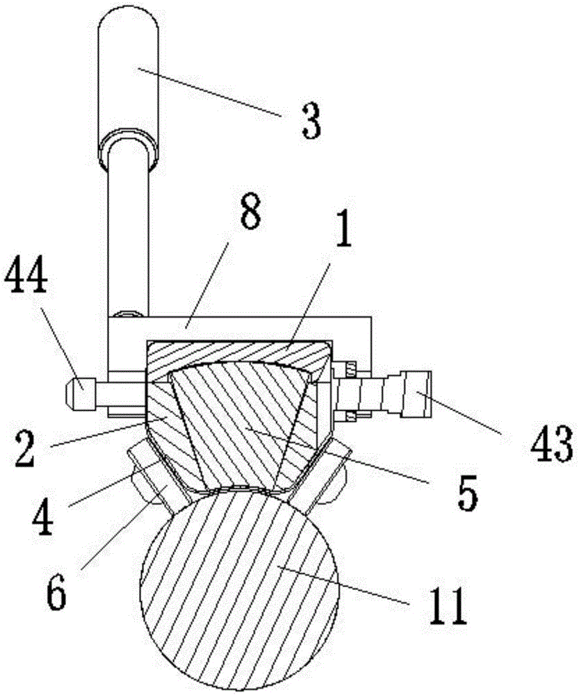
[0023] as attached Figure 1-4 As shown, an electromagnetic ultrasonic transducer without end detection blind zone according to the present invention includes a magnetic upper casing 1 and a non-magnetic lower casing 2, and a traction handle 3 for holding and operating; The lower casing 2 is provided with a high-frequency coil 4 and two permanent magnets 5 with the same magnetic pole direction, and a flame-retardant insulating material is filled between the permanent magnet 5 and the lower casing 2; the upper casing 1 is installed on the lower casing 2, so that two permanent magnets 5 are adsorbed on the upper casing 1 in parallel with each other; Cooperate with the lower housing 2, the rear end cover 8 clamps the upper housing 1 on the lower housing 2 at the rear side, the traction handle 3 is obliquely fixed on one side of the rear end cover 8, and the front end cover 7 has an anti-c...


PUM


Abstract

The invention discloses an electromagnetic ultrasonic transducer of an end portion-free detection blind area. The electromagnetic ultrasonic transducer comprises a magnetic upper shell and a non-magnetic lower shell, and a traction handle used for holding and operating; the lower shell is provided with a high frequency coil and two permanent magnets with a same magnetic pole direction, the two permanent magnets respectively have a sector-shaped structure with wide top and narrow bottom, the high frequency coil gets around the lower side of one of the permanent magnets to form an excitation end; the upper shell fits with the upper portion of the lower shell to make the two permanent magnets be adsorbed on the upper shell in a mutual parallel manner; and two sides of the lower portion of the lower shell are symmetrically provided with a plurality of rigid wheels. The electromagnetic ultrasonic transducer of the end portion-free detection blind area, adopting the above design, has the advantages of increasing of the intensity and the signal to noise ratio of a magnetic field and a signal, convenient use and operate, realization of convenient replacement of the coil, protection of the coil from being damaged, elimination of the detection blind area, and effective protection of the surface of a workpiece.

Description

technical field [0001] The invention relates to an ultrasonic transducer, in particular to an electromagnetic ultrasonic transducer mainly used for the nondestructive detection of the surface of bar and pipe material, the overall nondestructive detection of guided wave of pipe material and the non-end detection blind area of ​​thickness measurement detection. Background technique [0002] Currently commonly used electromagnetic ultrasonic transducers (EMAT) mostly use permanent magnets plus high-frequency coils; the permanent magnets provide a constant magnetic field for exciting ultrasound, and the high-frequency coils are used to excite and receive electromagnetic ultrasound. Magnetic field) and the workpiece under test constitute an electromagnetic ultrasonic excitation system; the electromagnetic ultrasonic generated by the electromagnetic ultrasonic excitation system has two effects, the Lorentz force effect and the magnetostrictive effect; when the measured workpiece is...

Claims


Application Information

Patent Timeline
Patent Type & Authority Applications(China)
IPC IPC(8): G01N29/04G01B17/02
CPCG01B17/02G01N29/04
Inventor 朱绪祥徐建强沈宇平周新宗杨龙
Owner SUZHOU PHASERISE TECH
Why Eureka
Try Eureka