Acceleration detector based on resonance light tunneling effect and detection method

A technology of tunneling effect and acceleration, which is applied in speed/acceleration/shock measurement, acceleration measurement, instruments, etc., which can solve problems affecting the measurement accuracy of accelerometers, increasing the difficulty of processing technology, and bending deformation of conductive films.

Active Publication Date: 2016-05-04
山西清众科技股份有限公司
View PDF8 Cites 2 Cited by
  • Summary
  • Abstract
  • Description
  • Claims
  • Application Information

AI Technical Summary

Problems solved by technology

However, in the process of realizing the acceleration measurement, the conductive film may have bending deformation, which will affect the measurement accuracy of the accelerometer
At the same ti...

Method used


Image

  • Acceleration detector based on resonance light tunneling effect and detection method
  • Acceleration detector based on resonance light tunneling effect and detection method
  • Acceleration detector based on resonance light tunneling effect and detection method

Examples


Embodiment 1

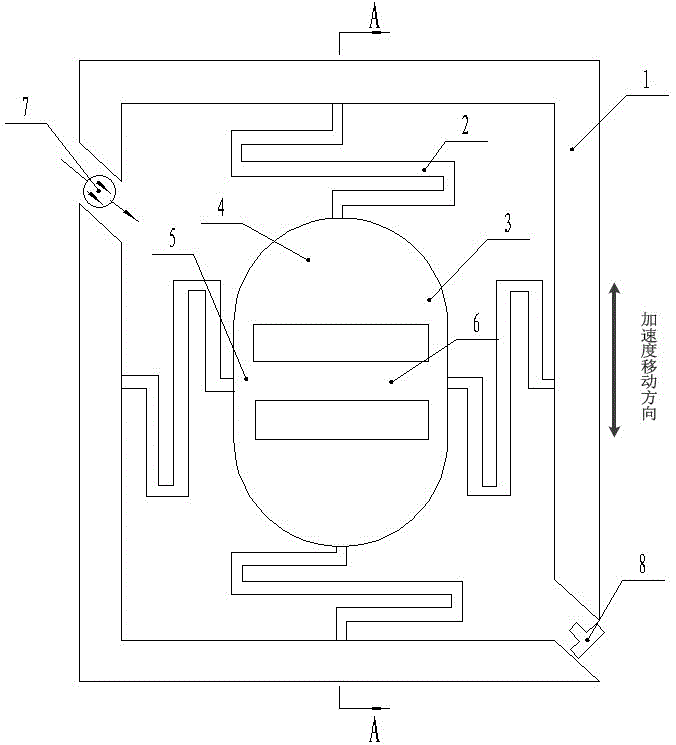
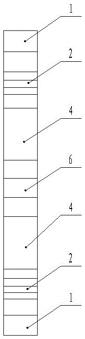
[0065] Such as Figure 1-3 As shown, an acceleration detector based on resonant light tunneling effect, including a fixed frame 1, an elastic cantilever beam 2 and a mass block 3,

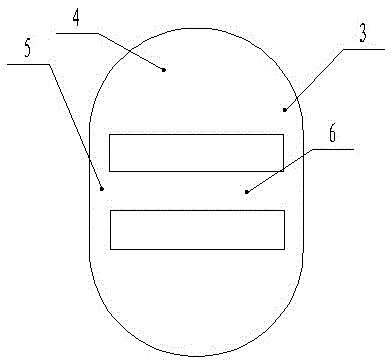
[0066] The mass block 3 is composed of a semi-cylindrical unit 4, a cuboid unit 5 and a resonance unit 6. The number of the semi-cylindrical unit 4 and the cuboid unit 5 is two, and the resonance unit 6 and two cuboid units 5 are connected to form an I-shaped structure. The two cuboid units 5 are two parallel beams of I-shaped structure, the square faces of the two semi-cylindrical units 4 are opposite and connected by the I-shaped structure, the resonance unit 6 is parallel to the square faces of the semi-cylindrical unit 4; the semi-cylindrical unit 4. Two gaps are formed between the cuboid unit 5 and the resonant unit 6 to form two resonant cavities; the mass block 3 is formed by etching an oblong silicon chip;

[0067] There are four elastic cantilever beams 2, four elastic cantilever beams 2 ...

Embodiment 2

[0070] Select the wavelength λ of the incident light to be 1550nm, the angle between the direction of the incident light and the positive direction of the X-axis is always β, and the incident light is P-polarized light; the width of the resonance unit 6 is g λ =15.622μm, air layer width d λ =2280nm, the refractive index of air is 1.

[0071] Since the quality block is made of silicon, the refractive index of silicon is 3.42, so the critical angle θ is obtained according to Snell's law of refraction c is 17.0016 degrees, and this embodiment selects the initial incident angle as α 0 It is 17.9516 degrees, and the variation range of displacement is controlled within 150nm.

[0072] According to the above conditions, through simulation calculation, the change curve (fitting curve) of light transmission intensity T with angle change Δθ is as follows Figure 7 As shown, the change curve of the light transmission intensity T with the displacement ΔH is as follows Figure 8 shown....


PUM

PropertyMeasurementUnit
Widthaaaaaaaaaa

Abstract

The invention relates to an acceleration detector based on the resonance light tunneling effect and a detection method. According to the acceleration detector, the high-resolution characteristic of the resonance light tunneling effect principle is utilized to measure acceleration, and the acceleration detector is in a novel structure. The acceleration detector based on the resonance light tunneling effect comprises a fixing frame, an elastic cantilever beam and a quality block, wherein an adjustable light source and a photoelectric detector are fixed on the fixing frame. The resonance light tunneling effect is utilized to detect large change amount of transmission intensity (i)T(/i) caused by tiny shift amount change of the quality block, so displacement amount can be acquired through monitoring the light transmission intensity change, and thereby accurate measurement on the micro displacement amount can be realized.

Description

technical field [0001] The invention relates to an acceleration detector, in particular to an acceleration detector and a detection method based on the principle of resonant light tunneling effect. Background technique [0002] At present, accelerometers are used in many fields, such as measuring the collision strength of cars in traffic accidents, detecting the acceleration performance of aircraft, and the vibration intensity of bridges under the influence of external environments. Under the condition of rapid development of micro-electro-mechanical systems (MEMS) technology, micro-mechanical accelerometers, known for their low power consumption, easy integration, small size, and small weight, stand out and become the core device of the micro-inertial measurement combination. Commonly used MEMS accelerometers include capacitive and piezoresistive accelerometers, and capacitive accelerometers mainly include cantilever beams and mass blocks. For capacitive accelerometers, du...

Claims


Application Information

Patent Timeline
IPC IPC(8): G01P15/00
CPCG01P15/00
Inventor 菅傲群段倩倩魏重光桑胜波张文栋唐军石云波
Owner 山西清众科技股份有限公司
Why Eureka
Try Eureka