
Liquid injection machine and liquid injection units thereof

A liquid injection machine and liquid injection technology, applied in the field of liquid injection machines, can solve the problems of low liquid injection efficiency, at most ten or twenty, expensive, and cheap ones costing several thousand yuan per unit, etc. The effect of reducing the cost of liquid injection and improving the efficiency of liquid injection

Active Publication Date: 2016-05-04
常熟东南高新技术创业服务有限公司
View PDF3 Cites 2 Cited by
  • Summary
  • Abstract
  • Description
  • Claims
  • Application Information

AI Technical Summary

Problems solved by technology

Quantitative liquid injection pumps are relatively expensive, and the cheap ones cost several thousand yuan each. For batch batteries, such as 700 batteries, it is impossible to make one battery cell correspond to one liquid injection pump. Therefore, the current liquid injection machine injects The liquid efficiency is relatively low, and a cycle of liquid injection is at most a dozen or twenty batteries

Method used


Image

  • Liquid injection machine and liquid injection units thereof
  • Liquid injection machine and liquid injection units thereof
  • Liquid injection machine and liquid injection units thereof

Examples


Embodiment Construction

[0033] The present invention will be further described in detail below through specific embodiments in conjunction with the accompanying drawings.

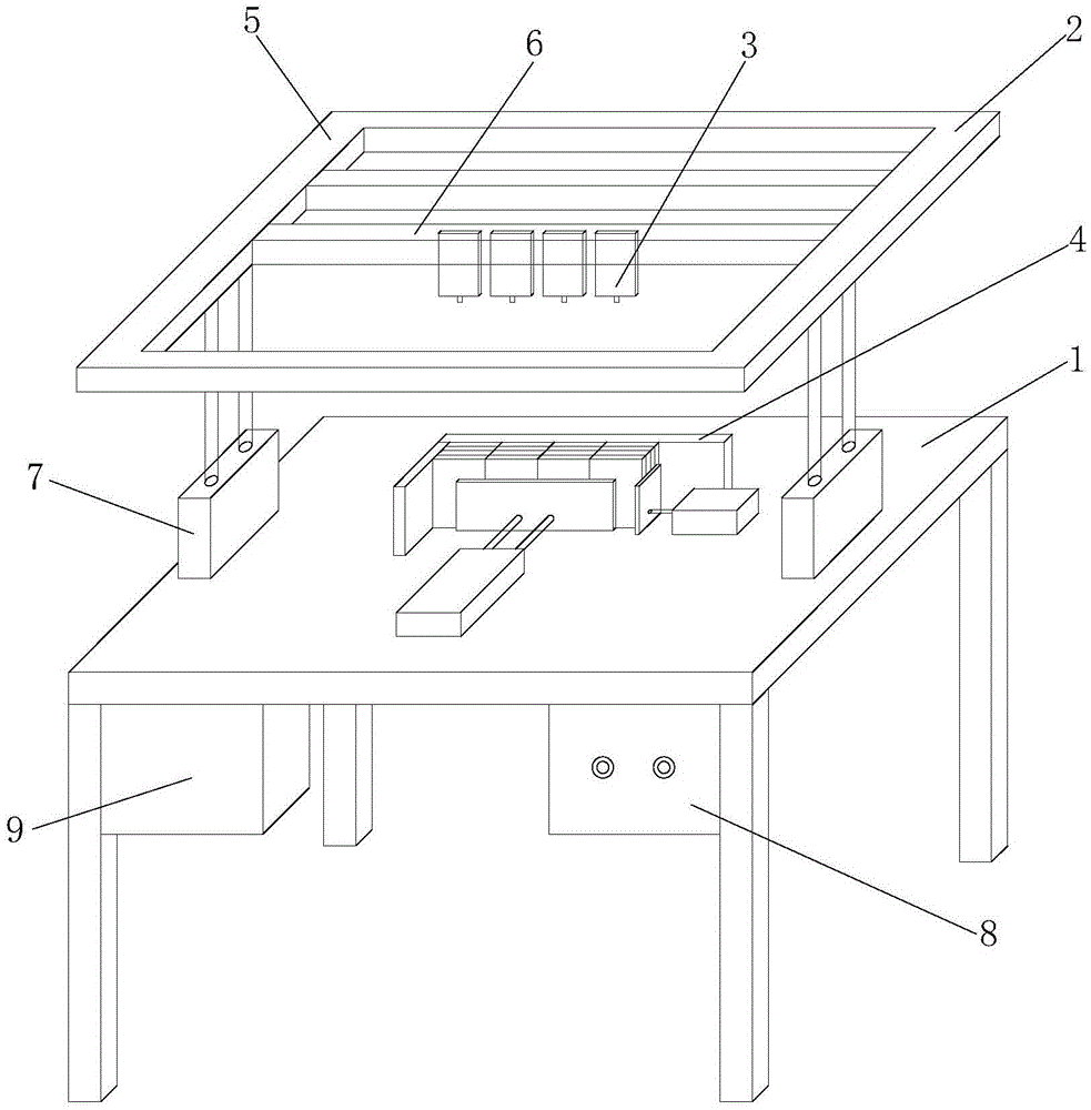
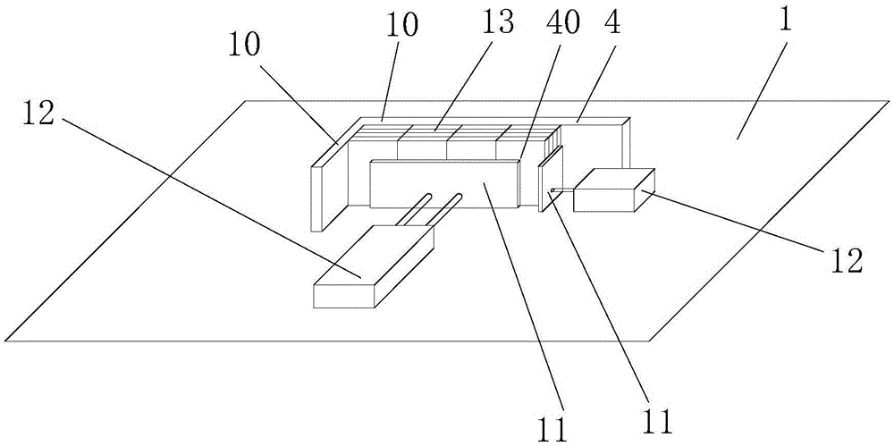
[0034] Such as Figure 1 to Figure 8 As shown, the liquid injection machine in this embodiment includes an electrical control box 8 , a machine platform 1 , a lifting device 2 , a liquid injection unit 3 , a cell positioning jig 4 and a solenoid valve group 9 .

[0035] Such as figure 1 As shown, the lifting device 2 includes a frame 5 , a beam 6 and a lifting cylinder 7 . The 7 sleeve ends of the lifting cylinder are vertically fixed on the plane of the machine platform 1, the 7 shaft ends of the lifting cylinder are fixed with the frame 5 and drive the frame 5 to move up and down, and the cross beam 6 is fixed on the frame 5 and its position can be adjusted. The liquid injection unit 3 is fixed on the beam 6 and its position can be adjusted up, down, left, and right. Both the positions of the crossbeam 6 and the liquid inject...


PUM


Abstract

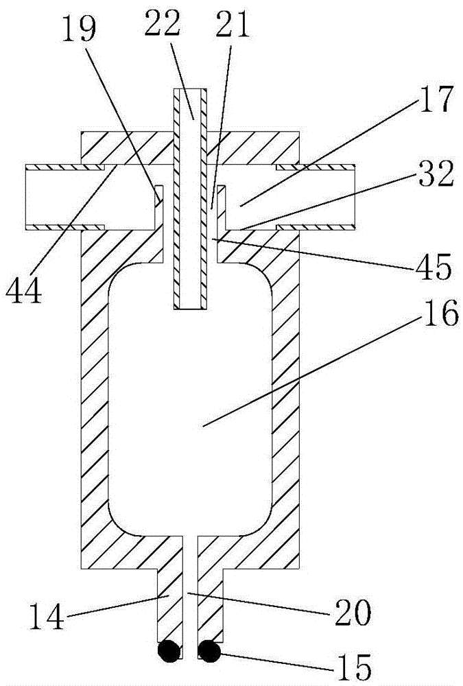
The invention discloses a liquid injection machine and liquid injection units thereof. The liquid injection machine comprises a machine table, a lifting device, an electromagnetic valve bank, a battery core positioning clamp, at least two liquid injection units and a liquid injection pump, wherein the liquid injection pump is used for injecting liquids into the liquid injection units; the liquid injection units are located at the upper part of the battery core positioning clamp; the lifting device drives the liquid injection units to lift and drop; each liquid injection unit comprises an injection nozzle, a volume chamber, a liquid pipe and a gas hole; the lower part of each volume chamber is communicated with the corresponding injection nozzle; the upper part of each volume chamber is communicated with the corresponding gas hole; the upper part of each liquid pipe extends outside upwards; the lower part of each liquid pipe extends into the corresponding volume chamber downwards; each liquid pipe, each gas hole and each volume chamber are communicated with one another; the gas holes of the liquid injection units are sequentially connected end to end in series to form a gas channel; the electromagnetic valve bank comprises a plurality of electromagnetic valves; and the battery core positioning clamp comprises a positioning space. The liquid injection machine can accurately inject the liquids into battery cores in large quantities by a common pump within a cycle, so that the liquid injection efficiency is greatly improved; and the liquid injection cost is reduced.

Description

technical field [0001] The present application relates to a liquid injection machine. Background technique [0002] The lithium battery (battery core) includes a shell, a core and an electrolyte. The shell includes a shell and a cap. The cap has a rivet (electrode) insulated from the cover (a part of the shell), and the shell seals the core and the electrolyte. , the winding core is wound together by the positive electrode sheet, the diaphragm, and the negative electrode sheet. For aluminum shell batteries, the positive electrode sheet is connected to the casing from the inside through the positive connecting conductor, and the positive electrode of the winding core is led to the casing, and the negative electrode sheet is connected to the casing through the negative connecting conductor. It is connected with the rivet (electrode) of the cap, and the negative pole of the winding core is drawn out of the battery case. The shell is divided into two types: cube and cylinder ac...

Claims


Application Information

Patent Timeline
Patent Type & Authority Applications(China)
IPC IPC(8): H01M2/36H01M6/14H01M10/058H01M50/609
CPCH01M6/14H01M10/058H01M50/60Y02E60/10Y02P70/50
Inventor 丁振荣
Owner 常熟东南高新技术创业服务有限公司
Learn More