Check patentability & draft patents in minutes with Patsnap Eureka AI!

Method and apparatus for generating compressed air flow and method and apparatus for cryogenically separating air

A low temperature, equipment technology, applied in the field of generating compressed air flow, can solve problems such as no satisfactory solution has been found, and achieve the effect of compact design scheme

Inactive Publication Date: 2018-02-09
LINDE AG
View PDF21 Cites 0 Cited by
  • Summary
  • Abstract
  • Description
  • Claims
  • Application Information

AI Technical Summary

Problems solved by technology

No satisfactory solution has been found so far for this problem

Method used


Image

  • Method and apparatus for generating compressed air flow and method and apparatus for cryogenically separating air
  • Method and apparatus for generating compressed air flow and method and apparatus for cryogenically separating air

Examples


Embodiment Construction

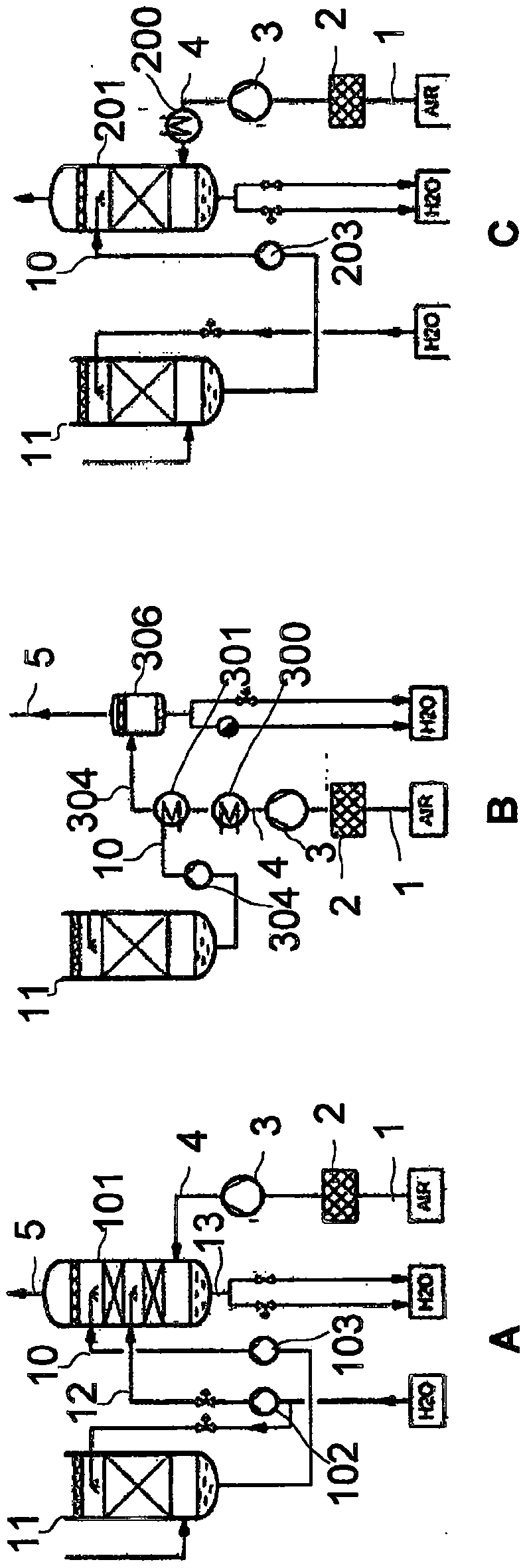
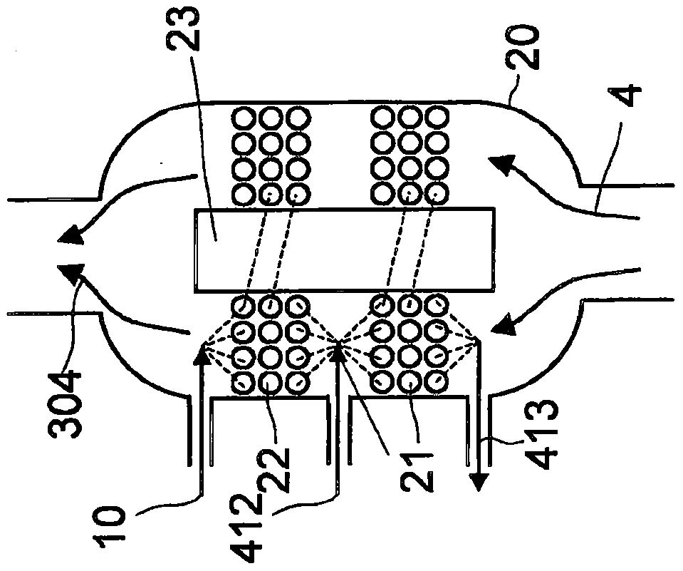
[0026] A first tube bundle 21 and a second tube bundle 22 are arranged in a common pressure vessel 20 . The tubes of the two tube bundles 21 , 22 are each helically wound on different axial sections of a core tube 23 . In the main air compressor ( figure 1 The hot feed air 4 compressed in 3) in B flows into the vessel from below, passes by the first tube bank 21 and the second tube bank 22 and is cooled there. A pre-cooled feed air stream 304 is drawn at the head of vessel 20 .

[0027] At the upper end of the second tube bundle 22 the cold water 10 is introduced into the interior of the tube as "second cooling fluid". The heated second cooling fluid discharged at the lower end of the second tube bundle is collected in the collector, mixed with the cooling water 412, and sent to the upper end of the first tube bundle 21 through the distributor as "first cooling fluid". (collectors and allocators in figure 2 Not shown in schematic. ) The water 413 discharged from the lowe...


PUM


Abstract

The invention relates to a method and a device used to produce a compressed gas flow (304, 5) and which can be used, for example, in a method or a device for separating air at a low-temperature. Compression heat is removed from a gas flow (1) compressed in a gas compressor in a two-step cooling unit which is formed by a first and a second bundle (21, 22) of helically wound tubes, both bundles (21, 22) being arranged in a common container (20).

Description

technical field [0001] The present invention relates to a method of generating a compressed gas stream. The cooling unit of the invention has at least two stages, including impossible subsequent equipment, for example, purification equipment or a main heat exchanger for further cooling to cryogenic temperatures. The invention can in principle be applied to all gas compression methods, irrespective of other applications of the compressed gas stream. They are especially applicable to systems in which the feed stream of a gas separation unit or the product or intermediate product stream from a gas separation unit is subjected to elevated pressure. Background technique [0002] Related methods with two-stage cooling units are known, especially at low temperatures for separate generation of feed air streams, where they are used for so-called precooling of the feed air. At this point, the feed air is compressed in the main air compressor (MAC=Main Air Compressor), which generall...

Claims


Application Information

Patent Timeline
Patent Type & Authority Patents(China)
IPC IPC(8): F25J3/04
CPCF25J3/04157F25J5/002F28D7/0091F28D7/024
Inventor M·佐策克D·戈卢贝夫S·阿勒拉巴迪
Owner LINDE AG
Features
  • R&D
  • Intellectual Property
  • Life Sciences
  • Materials
  • Tech Scout
  • Unparalleled Data Quality
  • Higher Quality Content
  • 60% Fewer Hallucinations
Learn More