Compound robot heat source welding system by double methods of friction stud and friction stir

A friction stir and composite heat source technology, applied in welding equipment, non-electric welding equipment, metal processing equipment, etc., can solve problems such as inability to complete, unable to meet intelligent, flexible manufacturing, and small application scope, saving equipment costs, The effect of improving welding efficiency and welding quality

Active Publication Date: 2016-05-11
NANJING UNIV OF SCI & TECH
View PDF6 Cites 6 Cited by
  • Summary
  • Abstract
  • Description
  • Claims
  • Application Information

AI Technical Summary

Problems solved by technology

However, the application range of the above-mentioned equipment is relatively small and cannot meet the requirements of intelligent and flexible manufacturing. For example, the gantry friction stir welding equipment can only complete the butt weld welding of plates and plates, and the horizontal

Method used


Image

  • Compound robot heat source welding system by double methods of friction stud and friction stir
  • Compound robot heat source welding system by double methods of friction stud and friction stir
  • Compound robot heat source welding system by double methods of friction stud and friction stir

Examples


Embodiment 1

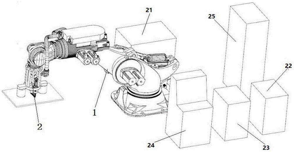
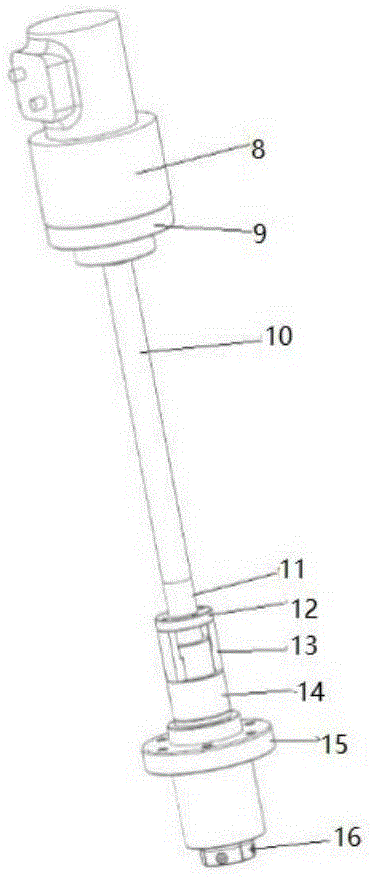
[0040] first step, such as image 3 As shown, the robot arm transports the collet 16 to the stud, and the preset program distributes signals to the hydraulic station 21 through the control cabinet 24 of the industrial computer, and the hydraulic station 21 controls the rotary cylinder 8 to pull the collet 16 upwards, thereby Automatically clamp the stud to complete the first step.

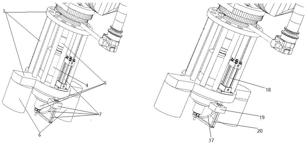
[0041] In the second step, the robot arm 1 drives the stud to move to the welding point. At this time, the induction coil 20 image 3 In the position shown, the industrial computer control cabinet 24 sends a signal to the hydraulic station 21 to control the hydraulic cylinder 18 of the induction coil 20 movement mechanism, thereby driving the induction coil 20 to move to the front end of the stud. Figure 4 Location.

[0042] In the third step, the induction coil 20 is energized to preheat the workpiece and the stud for a certain period of time, the spindle motor 4 is energized and rotates at a s...

Embodiment 2

[0045] In the first step, the welding head clamps the stirring needle, and drives the stirring needle and the induction coil 20 to move to the welding point. At this time, the induction coil 20 is Image 6 In the position shown, the workpiece is preheated for a certain period of time, and the protective gas is passed through the protective gas pipe 17 during the preheating process.

[0046] In the second step, the spindle motor 4 drives the stirring needle to rotate according to the set speed, and is pressed into the joint of the workpiece under the pressure of the mechanical arm 1. Figure 7 As shown, the friction stir welding is carried out along the butt joint, while the induction coil 20 preheats the unwelded butt joint, specifically as Figure 8 shown.

[0047] The third step, such as Figure 9 The shown friction stir welding is completed, the stirring needle leaves the weld, the induction coil 20 and the shielding gas of the shielding gas pipe 17 are closed, and the we...


PUM

PropertyMeasurementUnit
Diameteraaaaaaaaaa
Diameteraaaaaaaaaa
Center hole diameteraaaaaaaaaa

Abstract

The invention provides a compound robot heat source welding system by double methods of friction stud and friction stir. The system comprises an actuation mechanism and a control system, wherein the actuation mechanism includes robot arms and a welding machine head; and the welding machine head includes a bearing frame, a main shaft motor, an automatic fixture device, an electromagnetic pressing device and an inductive heating device. The system integrates friction stir with friction stud welding, facilitates to promote welding efficiency and welding quality, saves the equipment cost, and can realize welding of a stud with a larger diameter through selecting the inductive heating device to heat and the electromagnetic pressing device to apply pressure. A control system is used for controlling actions of all procedures of the welding system to realize the welding process and the function switching automation; and a hydraulic revolving oil cylinder is used for controlling a spring chuck to automatically clamp and loosen the stud and a stirring needle so as to completely realize automatic welding.

Description

technical field [0001] The invention relates to the field of intelligent welding, in particular to a friction stud and friction stirring dual-method robot composite heat source welding system. Background technique [0002] Most of the existing industrial robots are light-loaded robots, and the general load will not exceed 500KG. For the friction stud welding technology, the requirements for the load capacity of the robot are relatively high, and the robot is required to provide a force of more than 15KN. The largest robot in the stage can only carry a load of 1.3 tons, which cannot meet the needs of friction stud welding. [0003] Friction stir welding and friction stud welding are both advanced friction welding techniques. They both use friction heat and plastic deformation heat as the welding heat source. The difference is that the friction stir welding process is that a cylinder or other shaped stirring needle is inserted into the workpiece. At the joint of the joint, th...

Claims


Application Information

Patent Timeline
IPC IPC(8): B23K28/02B23K20/12
CPCB23K20/122B23K20/127B23K28/02
Inventor 周琦姚峰王克鸿彭勇冯曰海余进刘玲丹周传昆周春东徐振振段梦伟
Owner NANJING UNIV OF SCI & TECH
Why Eureka
Try Eureka