Overturning clamping device

A technology of clamping device and clamping mechanism, which is applied in the direction of auxiliary devices, auxiliary welding equipment, welding/cutting auxiliary equipment, etc., can solve the problems of time-consuming and labor-intensive, and achieve manpower saving, good application prospects, and easy alignment operation Effect

Active Publication Date: 2016-05-11
柳州市楷都汽车零部件有限公司
View PDF8 Cites 1 Cited by
  • Summary
  • Abstract
  • Description
  • Claims
  • Application Information

AI Technical Summary

Problems solved by technology

The previous welding work was mostly done manually, which was not only time-consuming and labor-intensive, but also had major problems in controlling the quality of the welding points. Automatic welding became the best choice. However, during the automatic welding process, the girder The clamping, how to control the size of the butt joint of the girders, and the positioning of the solder joints are all problems that need to be overcome.

Method used


Image

  • Overturning clamping device
  • Overturning clamping device
  • Overturning clamping device

Examples


Embodiment 1

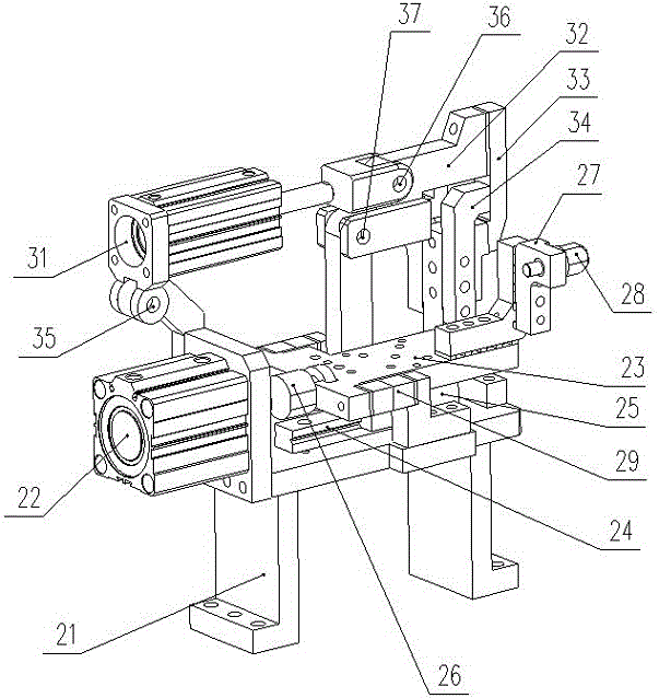
[0025] Embodiment 1: A flipping clamping device, including a workbench 1, a front and back clamping mechanism 2, a side clamping mechanism 4, a foot support I21, and a foot support II41, and the front and back clamping mechanism 2 passes through The foot support I21 is installed on the workbench 1, and the side clamping mechanism 4 is installed on the workbench 1 through the foot support II41, which is characterized in that:

[0026] The front and back clamping mechanisms 2 are provided with two groups, respectively corresponding to the two ends of the parts; each set of front and back clamping mechanisms 2 is composed of two clamping working parts I and two turning working parts I, and in each group The two clamping working parts I are respectively located on the front and back of the part, corresponding to each other;

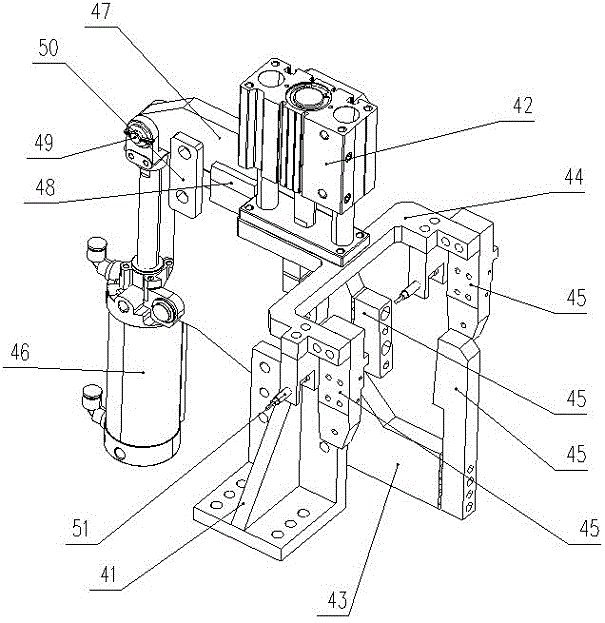
[0027] The side clamping mechanism 4 is arranged in the middle of the corresponding part; the side clamping mechanism 4 includes a clamping working part II a...

Embodiment 2

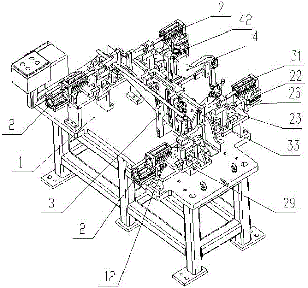
[0042] Embodiment 2: A robot welding production line for the rear beam assembly of a passenger car, which uses the overturning clamping device as described in Embodiment 1, and also includes a welding work plate 5, a spot welding robot arm 6 and a safety grating 7; The welding work disk 5 can be rotated, on which at least two groups of flip clamping devices are installed along the circumference, and the spot welding robot hand 6 is arranged in the middle of the welding work disk 5, and its mechanical arm and welding torch can cover all The welding points of the parts clamped by the flip clamping device; the safety grating 7 is set at the passageway for personnel to sense whether people or other objects stay in the working area.

[0043] After the first operator positions and clamps the components of the girder in the welding production line, the spot welding robot 6 is given a start signal through the control button, and the spot welding robot 6 automatically performs spot weld...


PUM


Abstract

The invention provides an overturning clamping device. The overturning clamping device comprises a workbench, front side and rear side clamping mechanisms, a lateral clamping mechanism, first foot support bases and a second foot support base. The front side and rear side clamping mechanisms are installed on the workbench through the first foot support bases. The lateral clamping mechanism is installed on the workbench through the second foot support base. Two sets of the front side and rear side clamping mechanisms are arranged and correspond to the two ends of a part correspondingly. Each set of the front side and rear side clamping mechanisms is composed of two first clamping working sections and two first overturning working sections. The two first clamping working sections of each set of the front side and rear side clamping mechanisms are arranged on the front side and on the rear side of the part correspondingly. The lateral clamping mechanism is arranged by corresponding to the middle of the part and comprises a second clamping working section and a second overturning working section. The overturning clamping device is reasonable in structural design, low in cost, capable of accurately positioning and clamping the part and good in effect through combination of the front side and rear side clamping mechanisms with the lateral clamping mechanism.

Description

technical field [0001] The invention relates to a welding equipment for auto parts, in particular to a turning and clamping device. Background technique [0002] Automobile girder is the main load-bearing part of the truck, which bears almost all the weight of the goods. The quality of the girder affects the service life and driving safety of the vehicle. The stamping process is generally used to manufacture the automobile girder, and its deformation method is mainly bending. Therefore The beam plate has high requirements on formability, that is, the automobile frame steel plate must have good comprehensive properties, sufficient strength and toughness, good fatigue resistance, and cold formability. Therefore, when welding it, the reliability of the welding There are extremely high requirements for precision, dimensional accuracy and the firmness of solder joints. The previous welding work was mostly done manually, which was not only time-consuming and labor-intensive, but ...

Claims


Application Information

Patent Timeline
Patent Type & Authority Applications(China)
IPC IPC(8): B23K37/047B23K37/00
CPCB23K37/00B23K37/0461B23K37/047
Inventor 李志
Owner 柳州市楷都汽车零部件有限公司
Why Eureka
Try Eureka