Manufacturing method of tuning self-locking screw

A manufacturing method and self-locking screw technology, applied in the field of signal processing, can solve problems such as uneven interface between tuning hole and tuning screw sleeve, labor cost, processing cost, and long processing time, so as to ensure dimensional accuracy and surface quality, and save equipment and labor cost, good electrical conductivity and ductility

Inactive Publication Date: 2016-05-11
JOHNSON PRECISION ENG SUZHOU
View PDF6 Cites 2 Cited by
  • Summary
  • Abstract
  • Description
  • Claims
  • Application Information

AI Technical Summary

Problems solved by technology

[0003] The current common method of manufacturing filter cover plates usually uses pure copper materials or metal materials with electroplated copper on the surface, which is relatively expensive. On the one hand, the stamping method is easy to damage the cover plate, and the defective rate is high. On the other hand, the processed tuning hole needs to be additionally installed with a tuning screw sleeve. The installation of the tuning screw sleeve not only requires labor costs and processing costs, but at the same time, the additional tuning screw sleeve installed on the tuning hole is not stable, and it is easy to loosen after a period of time. Moreover, the interface between the tuning hole and the tuning screw sleeve is not smooth, which ultimately affects the actual tuning effect
[0004] In the preliminary processing of the blank of the screw, it is usually necessary to use a CNC machine tool for processing, which takes a long time, is time-consuming and labor-intensive, and the cost of the CNC machine tool itself is also very expensive, and the use of a CNC machine tool for processing will also consume the life of the machine tool. , the loss outweighs the gain

Method used


Image

  • Manufacturing method of tuning self-locking screw
  • Manufacturing method of tuning self-locking screw
  • Manufacturing method of tuning self-locking screw

Examples


Embodiment Construction

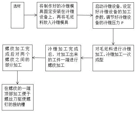
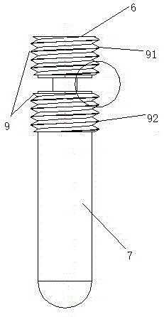
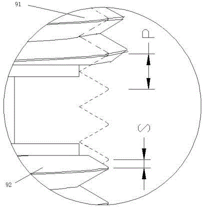
[0024] Embodiments of the present invention are described in detail below, examples of which are shown in the drawings, wherein the same or similar reference numerals designate the same or similar elements or elements having the same or similar functions throughout. The embodiments described below by referring to the figures are exemplary only for explaining the present invention and should not be construed as limiting the present invention.

[0025] In the description of the present invention, unless otherwise specified and limited, it should be noted that the terms "installation", "connection" and "connection" should be understood in a broad sense, for example, it can be mechanical connection or electrical connection, or two The internal communication of a component can be directly connected or indirectly connected through an intermediary. Those of ordinary skill in the art can understand the specific meanings of the above terms according to specific situations.

[0026] Re...


PUM


Abstract

A manufacturing method of a tuning self-locking screw comprises the following steps of selecting materials; fixedly mounting a manufactured cold upsetting die on cold upsetting equipment; then placing a prepared blank in the cold upsetting die; starting the cold upsetting equipment; setting machining parameters of the cold upsetting equipment, wherein the machining parameters comprise machining temperature, speed and the like; adjusting cold upsetting pressure P of the cold upsetting equipment; starting to carry out cold upsetting machining on the blank; forming at one step during cold upsetting machining; carrying out thread machining on one end of a machined workpiece after cold upsetting machining is finished, wherein two sets of threads are arranged and are not connected, screw pitches P between the upper set of threads and the lower set of threads are the same, the diameters of the upper threads are greater than the diameters of the lower threads, and a part between the two threads is machined until the diameter of the part is 40%-70% of the diameter of a non-machined part of the workpieceafter thread machining is finished; and forming an accommodating groove in the top of one end of each thread after a step seven is finished. Compared with the traditional mode of machining with a numerically-controlled machine tool, the manufacturing method of the tuning self-locking screw saves equipment cost and labor cost, and is better in effect.

Description

technical field [0001] The invention relates to the field of signal processing, in particular to a method for manufacturing a tuning self-locking screw. Background technique [0002] At present, the signal processing of the cavity filter is usually completed by the tuning self-locking screw on the filter cover. Generally speaking, the problem dealt with by the tuning screw is the problem of signal intermodulation. Specifically, it refers to two different frequency signals. A signal of a new frequency generated by superposition within a system. [0003] The current common method of manufacturing filter cover plates usually uses pure copper materials or metal materials with electroplated copper on the surface, which is relatively expensive. On the one hand, the stamping method is easy to damage the cover plate, and the defective rate is high. On the other hand, the processed tuning hole needs to be additionally installed with a tuning screw sleeve. The installation of the tu...

Claims


Application Information

Patent Timeline
Patent Type & Authority Applications(China)
IPC IPC(8): B23P15/00F16B35/04H01P1/207
CPCB23P15/00F16B35/04H01P1/207
Inventor 王强
Owner JOHNSON PRECISION ENG SUZHOU
Why Eureka
Try Eureka