
Cascade utilization system for blast furnace slag waste heat

A blast furnace slag and waste heat technology, which is applied in the field of blast furnace slag waste heat cascade utilization system, can solve the problems of further improvement of heat recovery efficiency, uneven slag particle shape and particle size distribution, unstable slag particle fluidization, etc., and achieves the carrying rate Low, reduced requirements for slag particle shape and size distribution, the effect of improved economy and reliability

Inactive Publication Date: 2016-05-11
UNIV OF SHANGHAI FOR SCI & TECH
View PDF4 Cites 4 Cited by
  • Summary
  • Abstract
  • Description
  • Claims
  • Application Information

AI Technical Summary

Problems solved by technology

The problem to be solved in this process is that the shape and size distribution of slag particles obtained during the granulation process of molten blast furnace slag is uneven, which will cause unstable fluidization of slag particles in the fluidized bed, high fluidization wind pressure, and low fan power consumption. High, the heat exchange tube wears quickly, the slag discharge temperature is high, and the heat recovery efficiency needs to be further improved

Method used


Image

  • Cascade utilization system for blast furnace slag waste heat

Examples


Embodiment Construction

[0013] The present invention will be further described below in conjunction with the accompanying drawings and embodiments.

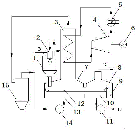
[0014] Such as figure 1 As shown, the blast furnace slag waste heat cascade utilization system of the present invention includes a separator 1, a molten blast furnace slag granulation device 2, a waste heat boiler 3, a steam turbine 4, a condenser 5, a generator 6, a gas collecting hood-7, a collector Air cover two 8, slag pit 9, air chamber two 10, air blower 11, cooling machine 12, air chamber one 13, circulation fan 14, dust collector 15.

[0015] Separator 1 is connected to molten blast furnace slag granulation device 2, the slag particle discharge pipe of separator 1 is connected to gas collection hood 17, the outlet of gas collection hood 1 7 is connected to waste heat boiler 3 inlet 1, and the gas discharge pipe of separator 1 is connected to waste heat boiler 3 Inlet 2 is connected, waste heat boiler 3 tail gas outlet is connected to dust colle...


PUM


Abstract

The invention relates to a cascade utilization system for blast furnace slag waste heat. A molten blast furnace slag granulating device is connected with a separator. A slag particle discharging pipe of the separator is connected with a first gas collecting cover. An outlet of the first gas collecting cover is connected with a first inlet of a waste heat boiler. A gas discharging pipe of the separator is connected with a second inlet of the waste heat boiler. A tail gas outlet of the waste heat boiler is connected with an inlet of a dust remover. An outlet of the dust remover is connected with an inlet of a circulating fan. An outlet of the circulating fan is connected with an inlet of a first wind chamber. An outlet of an air feeder is connected with an inlet of a second wind chamber. An outlet of the first wind chamber and an outlet of the second wind chamber are connected with a gas inlet in the bottom of a cooling machine. A gas outlet in the top of the cooling machine is connected with an inlet of the first gas collecting cover and an inlet of a second gas collecting cover. The tail end of the cooling machine is connected to a slag pit. Through the cascade utilization system, the functions that molten blast furnace slag is granulated, the blast furnace slag high-grade heat is recycled to generate steam used for generating electricity through a turbo generator set, the blast furnace slag low-grade heat is recycled to preheat air fed to a hot air furnace, tail gas is purified can be achieved. The utilization efficiency of the blast furnace slag waste heat is high, and the good energy-saving and environment-friendly effects are achieved.

Description

technical field [0001] The invention relates to a waste heat utilization system, in particular to a cascade utilization system of blast furnace slag waste heat. Background technique [0002] The iron and steel industry is an energy-intensive industry, and its energy consumption is about 10% to 15% of China's total energy consumption. Blast furnace slag is the most important waste in the iron and steel industry. About 300kg of blast furnace slag is produced per ton of iron. The temperature of the blast furnace slag is usually above 1400°C and contains very rich heat. Recycling and utilizing the waste heat of blast furnace slag can save energy and reduce emissions in the ironmaking industry Energy efficiency plays an important role. [0003] At present, the high-temperature slag discharged from the blast furnace is mainly quenched and granulated by the water flushing slag process, and the obtained cold slag is used as a raw material for cement production after dehydration. T...

Claims


Application Information

Patent Timeline
IPC IPC(8): C21B3/06C21B3/08F22B1/04
CPCC21B3/06C21B3/08F22B1/04Y02W30/50
Inventor 王波徐芳倩
Owner UNIV OF SHANGHAI FOR SCI & TECH
Learn More