Drilling device and hole forming method of pre-drilling type lateral pressure test

A technology of side pressure test and drilling device, which is applied in the field of foundation soil survey, construction, and infrastructure engineering, etc. Achieve the effect of shortening the construction period, not easy to disturb, and improving the quality of the hole

Active Publication Date: 2016-05-11
INST OF ROCK AND SOIL MECHANICS - CHINESE ACAD OF SCI
View PDF6 Cites 8 Cited by
  • Summary
  • Abstract
  • Description
  • Claims
  • Application Information

AI Technical Summary

Problems solved by technology

[0004] The purpose of the present invention is to overcome the deficiencies of the prior art. The present invention provides a drilling device for pre-drilling side pressure test, which can use ring cutters to cut soil and form a round, vertical and complete drilling device during the drilling process. The pre-drilling side pressure test drilling can effectively solve the problem of poor hole quality of the current pre-drilling side pressure, and provide another kind of pre-drilling with simple operation, low cost, small disturbance of the drilling hole wall, and high hole quality. Hole-forming method of type side pressure test, especially to solve the problem of easy-to-collapse holes in sandy soil stratum and easy-to-shrinkage holes in silt soil stratum

Method used


Image

  • Drilling device and hole forming method of pre-drilling type lateral pressure test
  • Drilling device and hole forming method of pre-drilling type lateral pressure test
  • Drilling device and hole forming method of pre-drilling type lateral pressure test

Examples


Embodiment 1

[0040] The object of this embodiment is a sandy soil stratum. A pre-drilling type side pressure test hole forming method and drilling device of the present invention are used to carry out a side pressure test. In order to compare the technical effects of the present invention, the side pressure test procedure (YS5224- 2000) the conventional pore-forming method was tested under the same conditions.

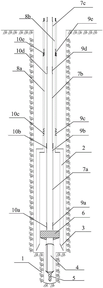
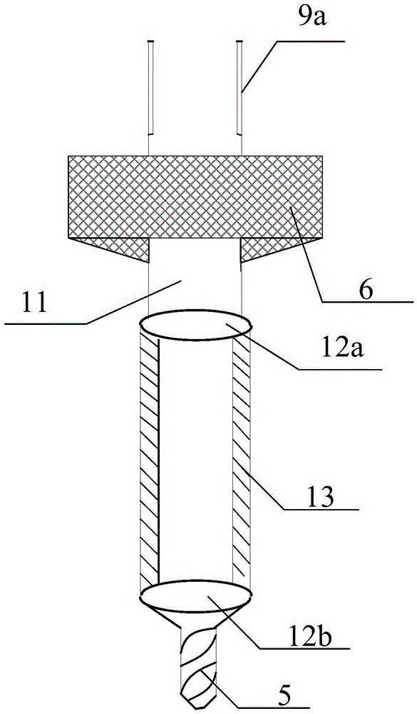
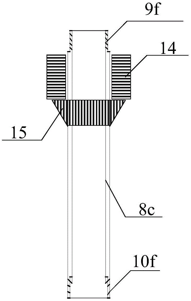
[0041] A kind of drilling device for pre-drilling side pressure test (see Figure 1 to Figure 4 ), which includes ring cutter soil cutter 2, spoon drill 4, drill bit 5, positioner 6, first drill rod 7a, second drill rod 7b, third drill rod 7c, first outer rod 8a, second outer rod 8b, the third outer rod 8c, the connecting rod 11, the first joint 12a, the second joint 12b, the drop weight 14 and the baffle 15.

[0042] Wherein, the top of the drill bit 5 is connected to the lower end of the spoon-shaped drill wall 13 through the second joint 12b, the upper end of the spoon-shaped d...

Embodiment 2

[0052] A kind of pre-drilling type bypass pressure test drilling device adopted by the second embodiment provided by the present invention is exactly the same as the device adopted in embodiment 1, and the test object is still the sandy soil formation with the same conditions. The drilling method of the pressure test is basically the same as that of Example 1, except that the mud protection wall is not carried out when drilling, the drilling speed of the drill pipe is 90 revolutions per minute, and the drilling stop standard is the lower end of the drill bit 5 or the ring cutter soil cutter 2 simultaneously. When the test depth of side pressure test is 0.5m, stop turning. Embodiment 2 adopts different mud wall protection measures, turning speed, and drilling stop standards from Embodiment 1 to test the influence of these control parameters on the quality of drilling holes and the reliability of side pressure test results.

[0053] The side pressure test curve of embodiment 2 i...

Embodiment 3

[0055] A kind of pre-drilling type lateral pressure test drilling method and drilling device adopted in the third embodiment provided by the present invention are completely the same as those adopted in embodiment 1, but the test object is the silt soil formation with the same conditions. At the same time, the side pressure test was carried out under the same conditions using the conventional pore forming method in the side pressure test procedure (YS5224-2000). To test a kind of pre-drilling type side pressure test drilling method and drilling device of the present invention in the silt soil layer drilling hole forming quality and side pressure test result reliability.

[0056] The side pressure test curve of embodiment 3 sees Figure 7 Shown, utilize a kind of pre-drilling type side pressure test pore forming method of the present invention in comparative example 3, and the side pressure test curve figure that conventional pore forming method obtains can find, adopt conventi...


PUM


Abstract

The invention provides a drilling device of a pre-drilling type lateral pressure test. The drilling device comprises a cutting ring soil miller, a spoon-type drill, a drill bit, a locator, drilling rods, outer rods, a connecting rod and a baffle. A hole forming method for carrying out the pre-drilling type lateral pressure test through the device comprises the steps that 1, an instrument is assembled, wherein the drill bit and the wall of the spoon-type drill are connected, the wall of the spoon-type drill is connected with the connecting rod, and the connecting rod is connected with the drilling rods; 2, drilling is carried out, wherein drilling is stopped when the locator is in contact with the ground surface, the center of the cutting ring soil miller is aligned to the locator to be vertically pressed into the underground, the baffle is arranged on the corresponding outer rod at the upper end of the cutting ring soil miller, and the cutting ring soil miller is vertically pressed into soil by pressing the baffle through the gravity of a drilling machine or hammering the baffle through a heavy hammer; 3, testing is carried out; and 4, drilling continues to be carried out, and the lateral pressure test of different depths in the same drilled hole is carried out. The device is simple in structure, detachable, convenient to manufacture and maintain, safe, stable, easy to operate, low in manufacturing cost, high in drilling speed and high in hole forming quality, the construction period can be remarkably shortened, and the adverse effect of hole collapse and hole shrinkage to the result of the lateral pressure test is eliminated.

Description

technical field [0001] The invention relates to the technical field of in-situ testing of geotechnical engineering, in particular to a drilling device suitable for forming a hole in a pre-drilling side pressure test, and also relates to a method for forming a hole in a pre-drilling side pressure test. Background technique [0002] In the field of geotechnical engineering, the mechanical properties of rock and soil are mostly obtained through laboratory tests and in-situ tests. Compared with the indoor test, the in-situ test can measure the engineering mechanical properties of the soil in the original position of the soil, basically maintain the natural structure, natural water content and natural stress state, which can avoid stress release and disturbance during the sampling process The influence of the obtained test results is more in line with the actual situation. The side pressure test is to use the side pressure instrument to apply radial pressure to the hole wall of ...

Claims


Application Information

Patent Timeline
Patent Type & Authority Applications(China)
IPC IPC(8): E02D1/04
CPCE02D1/025
Inventor 张先伟陈成尹松杨爱武李新明
Owner INST OF ROCK AND SOIL MECHANICS - CHINESE ACAD OF SCI
Why Eureka
Try Eureka