
Method and apparatus for determining measurement mode and tolerance of optical system parameters

A measurement mode and optical system technology, applied in the field of optical measurement, can solve problems such as difficult to meet the requirements of high sensitivity and precision measurement, and achieve the effect of suppressing measurement noise and improving accuracy

Active Publication Date: 2018-07-06
RAINTREE SCI INSTR SHANGHAI
View PDF6 Cites 0 Cited by
  • Summary
  • Abstract
  • Description
  • Claims
  • Application Information

AI Technical Summary

Problems solved by technology

This measurement method is difficult to meet the current high sensitivity and accuracy measurement requirements for different devices

Method used


Image

  • Method and apparatus for determining measurement mode and tolerance of optical system parameters
  • Method and apparatus for determining measurement mode and tolerance of optical system parameters
  • Method and apparatus for determining measurement mode and tolerance of optical system parameters

Examples


Embodiment Construction

[0023] In order to illustrate the solution of the present invention more clearly, the OCD measurement principle is first described below:

[0024] The implementation steps of the OCD measurement principle may include:

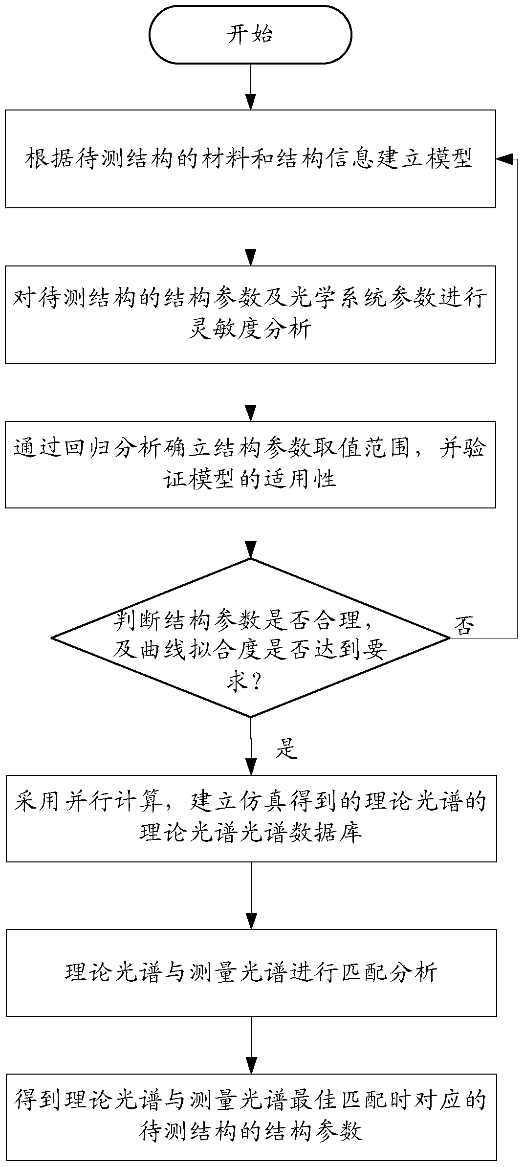
[0025] 1) The OCD measurement equipment establishes a theoretical spectral database corresponding to the morphology of the structure to be measured.

[0026] The specific implementation of this step includes: first, the OCD measurement device establishes the structure model to be measured according to the shape of the structure to be measured; then, the OCD measurement device performs theoretical simulation on the structure model to be measured according to the selected measurement mode and optical system parameters , to obtain the corresponding theoretical spectrum of the structure to be measured; then, the OCD measuring device establishes a theoretical spectrum database of the structure to be measured according to the theoretical spectrum of the structure to ...


PUM


Abstract

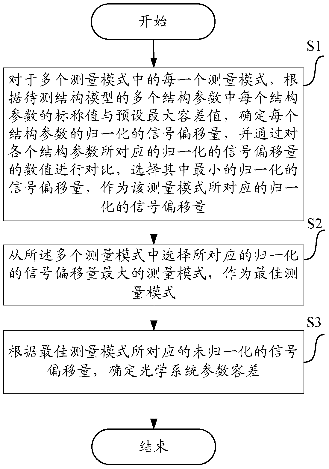
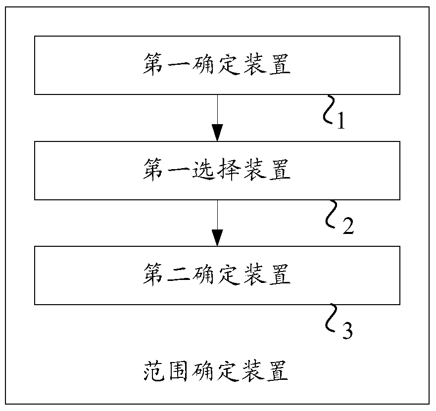
The present invention provides a scheme for determining the tolerance of optical system parameters in OCD measurement, wherein, for each of a plurality of measurement modes, the normalized signal offset; and from the Selecting the measurement mode with the largest normalized signal offset corresponding to the multiple measurement modes as the best measurement mode; and determining the Optical system parameter tolerances. According to the method of this embodiment, it is possible to determine the best measurement mode that meets the measurement sensitivity and accuracy requirements of each structural parameter, and determine the tolerance of each optical system parameter, thereby improving the measurement sensitivity and accuracy.

Description

technical field [0001] The present invention relates to the technical field of optical measurement, in particular to a kind of optical system parameter tolerance ( That is, the OCD method and device for measuring the maximum acceptable error range of each optical system parameter of the equipment. Background technique [0002] As the post-Moore era of the 2x nanotechnology node is approaching, the structural size of the device is getting smaller and smaller, and new processes and new materials introduce unique graphic design rules and measurement requirements, such as three-dimensional flash memory 3D (3-Dimensional) Flash, fin Type field effect transistor FinFET (Fin-Field-Effect-Transistor), immersion lithography, optical proximity correction OPC (Optical Proximity Correction), design-based measurement DBM (Design Based Metrology), double mask DP (Double Patterning), The introduction of 3D devices and new technologies, such as strained channel and chip stacking via techno...

Claims


Application Information

Patent Timeline
Patent Type & Authority Patents(China)
IPC IPC(8): G01B11/00G06F17/30B82Y35/00
Inventor 王鑫张振生施耀明徐益平
Owner RAINTREE SCI INSTR SHANGHAI
Learn More