
Combined loading test device

A test device and combined loading technology, which is applied in the direction of measuring device, wear resistance test, instrument, etc., can solve the problem of slow heating and cooling speed, insufficient temperature of high and low temperature cycle test chamber, and inability to meet the requirements of thermal shock test of engine hot end parts, etc. question

Inactive Publication Date: 2016-05-11
CHINA AIRPLANT STRENGTH RES INST
View PDF5 Cites 20 Cited by
  • Summary
  • Abstract
  • Description
  • Claims
  • Application Information

AI Technical Summary

Problems solved by technology

[0003] The temperature of the conventional high and low temperature cycle test chamber is insufficient, and the heating and cooling speed is slow, which cannot meet the thermal shock test requirements of the hot end parts of the engine
Due to the limitation of its own conditions, the traditional quartz lamp radiant heater is difficult to exceed 1200°C for a long time
Graphite radiation heating temperature is higher, but the heating environment needs vacuum or inert gas protection

Method used


Image

  • Combined loading test device

Examples


Embodiment Construction

[0033] In order to make the objectives, technical solutions and advantages of the present invention clearer, the technical solutions in the embodiments of the present invention will be described in more detail below in conjunction with the drawings in the embodiments of the present invention. In the drawings, the same or similar reference numerals denote the same or similar elements or elements having the same or similar functions throughout. The described embodiments are some, but not all, embodiments of the invention. The embodiments described below by referring to the figures are exemplary and are intended to explain the present invention and should not be construed as limiting the present invention. Based on the embodiments of the present invention, all other embodiments obtained by persons of ordinary skill in the art without creative efforts fall within the protection scope of the present invention.

[0034] In describing the present invention, it is to be understood th...


PUM


Abstract

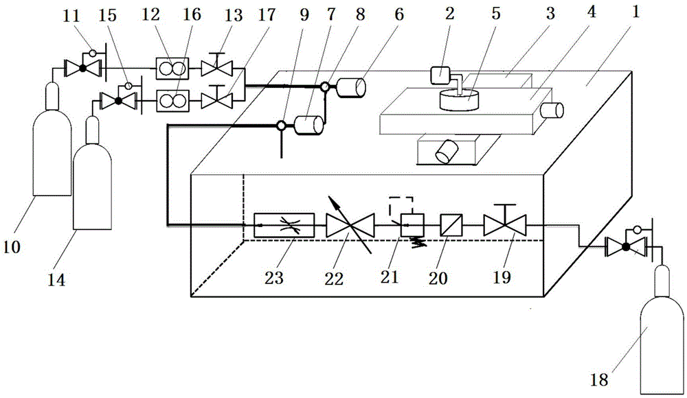
The invention relates to the field of thermal performance test and cooling efficiency test of thermal protection systems of aircraft, in particular to a combined loading test device. The combined loading test device comprises a test platform, a gas heating component which is used for heating a test piece, an air flow cooling component which is used for cooling the test piece, a temperature monitoring device which is used for acquiring the temperature information of the test piece in real time, and a control device which is used for controlling the gas heating component and the air flow cooling component according to the temperature information. According to the combined loading test device, the test piece is heated by the gas heating component, so that the disadvantages in the conventional heating mode are overcome; the shear effect caused by high-temperature air flow convection heating environment and air flow scouring, and the oxidation corrosion effect of a combustion product on the surface coating of a component when the test piece is used are truly simulated, and the working environment of the test piece can be truly simulated.

Description

technical field [0001] The invention relates to the fields of thermal performance testing and cooling efficiency testing of aircraft thermal protection systems, in particular to a combined loading test device. Background technique [0002] The rapid development of typical high-temperature thermal structures represented by aero-engine turbines and thermal protection systems for hypersonic vehicles has forced the continuous improvement of the application of new temperature-resistant materials and the cooling design of thermal structures. high demands. [0003] The temperature of the conventional high and low temperature cycle test chamber is insufficient, and the heating and cooling speed is slow, which cannot meet the requirements of the thermal shock test of the hot end parts of the engine. Due to the limitations of the traditional quartz lamp radiation heater, it is difficult to exceed 1200°C for a long time. Graphite radiation heating temperature is higher, but the heati...

Claims


Application Information

Patent Timeline
Patent Type & Authority Applications(China)
IPC IPC(8): G01N3/56G01N3/60
CPCG01N3/567G01N3/60
Inventor 霍施宇高翔燕群黄文由于
Owner CHINA AIRPLANT STRENGTH RES INST
Learn More