Anti-interference optical fiber perimeter protection system and method

A fiber optic perimeter and protection system technology, applied in anti-theft alarms, instruments, alarms, etc., can solve problems such as difficult to accurately identify human intrusions, and achieve the effects of easy follow-up maintenance, vibration suppression, and cost reduction

Active Publication Date: 2016-05-11
杭州安远科技有限公司
View PDF4 Cites 6 Cited by
  • Summary
  • Abstract
  • Description
  • Claims
  • Application Information

AI Technical Summary

Problems solved by technology

In non-bad weather conditions and uncomplicated environmental conditions, intrusion actions can be accurately determined. However, in harsh environments and more interference conditions, it is difficult to accurately identify human intrusions.
Especially in strong wind and rain, the signal generated by the vibration of the optical cable due to strong wind and rain is similar in strength and frequency to the signal generated by some man-made intrusion actions, so many false alarms will occur
To ensure that false alarms do not occur when it rains, some human intrusions cannot be judged as intrusions by the system under normal weather conditions.

Method used


Image

  • Anti-interference optical fiber perimeter protection system and method
  • Anti-interference optical fiber perimeter protection system and method
  • Anti-interference optical fiber perimeter protection system and method

Examples


Embodiment 1

[0059] The anti-interference optical fiber perimeter protection system of the embodiment of the present invention, the optical fiber perimeter protection system includes:

[0060] A sensing optical cable, the sensing optical cable is laid on the physical enclosure;

[0061] A collection device, the collection device is installed on the physical enclosure, and is used to collect the signal transmitted by the sensing optical fiber and send it to the processing and alarm device;

[0062] A processing and alarm device, the processing and alarm device is installed on the physical enclosure (installed in the same housing as the collection device), and is used to process the signal transmitted by the collection device and prompt an alarm as required; The laser is installed in the processing and alarm device, and the above-mentioned devices are all prior art in this field, and will not be repeated here.

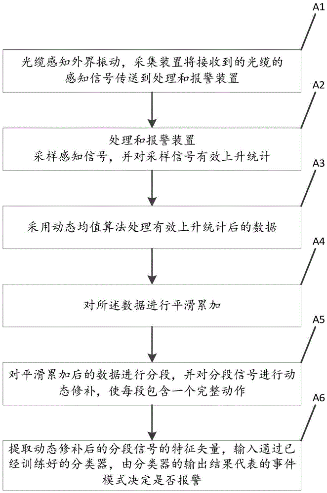
[0063] figure 1 A flow chart of the anti-interference optical fiber perimeter ...

Embodiment 2

[0091] An application example of the optical fiber perimeter protection system and method according to Embodiment 1 of the present invention.

[0092] In this application example, the fiber perimeter protection methods are as follows:

[0093] (A1) The optical cable installed on the fence is collided, and the vibration signal sensed by the optical cable is output to the processing and alarm device at the rear end through the acquisition device, and the processing and alarm device samples the received acquisition signal;

[0094] (A2) Schematic diagram of the effective rise of the statistical signal, set the crossover level to 2.048V, and the noise margin to 0.12V. The effective number of rises of each sampling signal containing 512 sampling data is the black rectangle mark, so the crossover after processing the signal is obtained The times are 8, 7, 6 respectively, such as Figure 5 As shown, the amount of data after statistical processing is only 1 / 512 of the original, which...


PUM


Abstract

The invention provides an anti-interference optical fiber perimeter protection system and a method. The optical fiber perimeter protection system comprises a sensing optical cable arranged on a physical perimeter; an acquisition device arranged on the physical perimeter and used for acquiring signals transmitted by the sensing optical cable and sending the signals to a processing and alarm device; and a processing and alarm device arranged on the physical perimeter and used for processing the signals transmitted by the acquisition device and prompting to give alarms according to the requirement. The system and the method are advantageous in that the anti-interference capability is high.

Description

technical field [0001] The invention relates to optical fiber perimeter protection, in particular to an optical fiber perimeter protection system and method capable of resisting wind and rain interference. Background technique [0002] With the continuous development of my country's economy and science and technology, people's awareness of safety precautions is getting stronger and stronger, and the safety precautions of living and living around schools, residential quarters, and industrial parks have become more and more concerned about people. Not only that, the perimeter security of complex environments such as oil fields, oil depots, power plants, and airports deserves special attention. Higher requirements are also put forward for the security of important areas related to national security, such as military sites, judicial prisons, and government agencies. Therefore, A safe and effective perimeter security monitoring system is particularly important. [0003] The trad...

Claims


Application Information

Patent Timeline
Patent Type & Authority Applications(China)
IPC IPC(8): G08B13/186
CPCG08B13/186
Inventor 邓志辉徐建伟韩晓阳
Owner 杭州安远科技有限公司
Why Eureka
Try Eureka