
Dynamic regulation apparatus for driving signal and driving method and driving system thereof

A technology for dynamic adjustment and driving of signals, applied in control/regulation systems, output power conversion devices, adjustment of electrical variables, etc., which can solve problems such as low average efficiency, large standby power consumption, and intractable electromagnetic interference.

Active Publication Date: 2016-05-11
HANGZHOU SILAN MICROELECTRONICS
View PDF5 Cites 16 Cited by
  • Summary
  • Abstract
  • Description
  • Claims
  • Application Information

AI Technical Summary

Problems solved by technology

Failure to optimize the drive of the MOS switch tube M1 will lead to difficult EMI (electromagnetic interference), lower average efficiency, and larger standby power consumption

Method used


Image

  • Dynamic regulation apparatus for driving signal and driving method and driving system thereof
  • Dynamic regulation apparatus for driving signal and driving method and driving system thereof
  • Dynamic regulation apparatus for driving signal and driving method and driving system thereof

Examples


Embodiment Construction

[0094] The present invention will be described in detail below in conjunction with the accompanying drawings and specific embodiments. Note that the aspects described below in conjunction with the drawings and specific embodiments are only exemplary, and should not be construed as limiting the protection scope of the present invention.

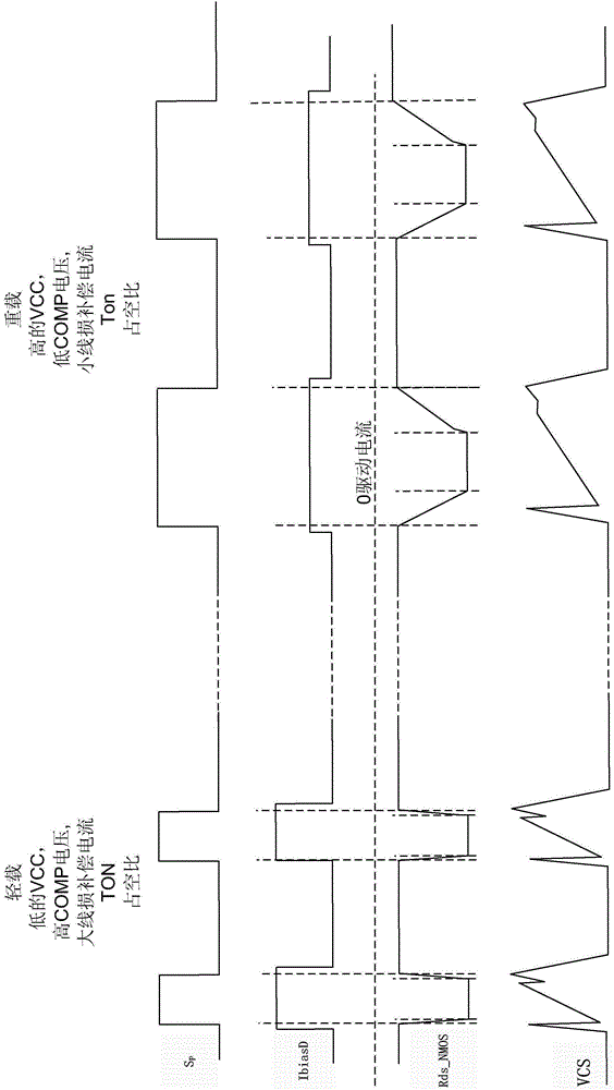
[0095] Traditional gate drive schemes are difficult to balance in terms of EMI and drive efficiency. EMI becomes more serious as the load increases. At this time, it is often necessary to reduce the driving capability to improve EMI. However, a driving scheme with a lower driving capability can certainly reduce EMI under a heavy load, but the EMI problem itself is not serious when the load is light, and the lower driving capability affects the driving efficiency at this time. On the other hand, if the driving capability is increased in pursuit of efficiency, the EMI problem will become more prominent under heavy load conditions.

[0096] ...


PUM


Abstract

The invention provides a dynamic regulation apparatus for a driving signal. The driving signal is used for driving an MOS switch tube to be switched on and switched off; the dynamic regulation apparatus comprises a pull-up MOS tube, a pull-down MOS tube and a controlled voltage source module, wherein a gate end receives a pull-up control signal used for controlling the gate end to be switched on and switched off; one of a source end and a drain end is coupled to a power supply voltage end while the other one of the source end and the drain end is coupled to a gate end of the MOS switch tube; the gate end receives a pull-down control signal used for controlling the gate end to be switched on and switched off; one of the source end and the drain end is coupled to a circuit ground end while the other one of the source end and the drain end is coupled to the gate end of the MOS switch tube; the controlled voltage source module is used for providing controlled voltage to the gate end of the pull-down MOS tube to enable the gate-source voltage of the pull-down MOS tube to be elevated to the power supply voltage at a dynamically adjustable speed when the pull-down MOS tube is started by the pull-down control signal, so as to drive the MOS switch tube to be switched on and switched off with variable driving capabilities.

Description

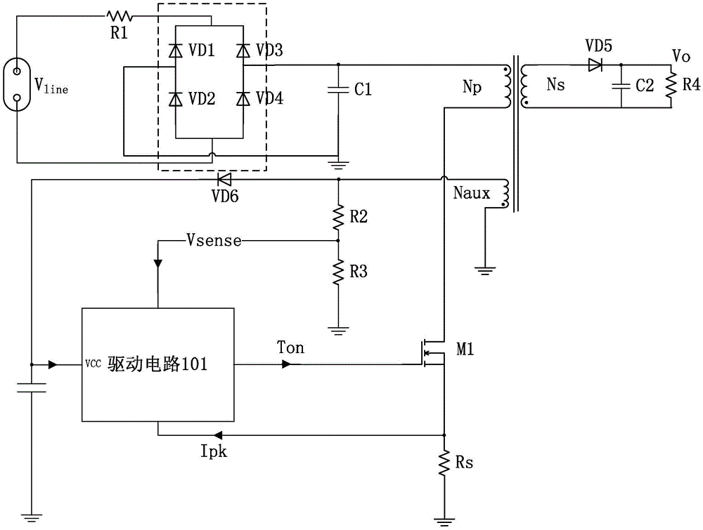
technical field [0001] The invention relates to a driving technology in a switching power supply, in particular to a dynamic adjustment device for a driving signal, a driving method and a driving system thereof. Background technique [0002] At present, in the small and medium output power off-line AC-DC conversion circuit, the primary side regulation (PSR) flyback converter adopts the primary feedback control technology to eliminate the feedback of optical isolation and the secondary power required in the traditional design. Regulate the circuit, simplify the design, and are widely used in home appliances and other fields. [0003] figure 1 It is a structural diagram of a typical primary-side control flyback AC-DC conversion circuit system. like figure 1 As shown, the change circuit includes an off-line AC-DC drive control circuit and peripheral circuits. [0004] see figure 1 , the general driving circuit 101 includes an output detection module and a Ton (on time) / Tof...

Claims


Application Information

Patent Timeline
IPC IPC(8): H02M1/088H02M3/335H02M1/44
CPCH02M1/088H02M1/44H02M3/33553
Inventor 张钦阳詹桦洪益文
Owner HANGZHOU SILAN MICROELECTRONICS
Learn More