Atomic force microscope-based material surface acid solution treatment mode

An acidic solution and surface smoothing technology, applied in the preparation of test samples, measuring devices, instruments, etc., can solve problems such as large charge, strong signal, difficult charge measurement and characterization

Pending Publication Date: 2021-09-24
HARBIN UNIV OF SCI & TECH
View PDF4 Cites 0 Cited by
  • Summary
  • Abstract
  • Description
  • Claims
  • Application Information

AI Technical Summary

Problems solved by technology

[0004] Due to the poor conductivity of most polymer materials, there will be strong self-generated charges on the surface of the sample, and due to the poor conductivity of most polymer materials, the charges inside and on the surface of the material are not easily moved, resulting in the observation of microprobes in small areas. Due to the large amount of overall charge, the signal is too strong to be distinguished, so it is difficult to measure and characterize the distribution and movement of charges on the microscopic scale by conventional means, so it is necessary to treat the surface of the sample to reduce the charge on the surface
[0005] Moreover, when the sample is observed with an atomic force microscope to observe the dielectric properties of nanodielectrics, there is often a problem that there are no nanoparticles on the surface, resulting in high experimental repeatability and inconspicuous experimental results. However, most experiments have not proposed effective solutions to this. The invention can fully expose the nanoparticles on the surface of the sample and obtain a better observation surface

Method used


Image

  • Atomic force microscope-based material surface acid solution treatment mode
  • Atomic force microscope-based material surface acid solution treatment mode
  • Atomic force microscope-based material surface acid solution treatment mode

Examples


Embodiment Construction

[0019] In the experiment, A200 hydrophilic nano-SiO2 produced by Degussa Company was selected as the introduction particle. Firstly, the nano-particles were put into an appropriate amount of alcohol to prepare a nano-particle dispersion, and then the dispersion was ultrasonically oscillated for 40 minutes to obtain a uniform nano-particle alcohol dispersion. liquid.

[0020] Put the polyethylene in a Hapro RM-A200 torque rheometer, set the temperature at 130°C, and drop the dispersion evenly when the polyethylene melts. After the dispersion liquid was dropped in, the sample was continuously stirred until the torque became stable, and then the sample was taken out to obtain the experimental material.

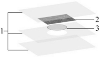
[0021] In order to make the surface of the sample smooth and fully expose the nanoparticles to the surface of the sample, the ultra-flat mica (2) surface is used to press the surface of the sample. First, the mica sheet is treated, and the surface of the mica sheet is glued down ...


PUM


Abstract

A material surface acid solution treatment mode based on an atomic force microscope is a surface treatment mode for an observed material. The invention aims to solve the problems of less exposure of nano particles and high surface potential when the surface is observed by using the atomic force microscope, and obtains a sample suitable for observation by the atomic force microscope after the sample is treated, so that more nano particles are exposed and the surface potential is reduced. The mode comprises the steps of pressing the nano composite material into a proper flaky sample by using a press vulcanizer, placing the sample, slowly dripping an acidic solution prepared from 5 parts of concentrated sulfuric acid, 2 parts of orthophosphoric acid, 1 part of 1% potassium permanganate and 1 part of water onto the surface of the sample until the surface is covered by the acidic solution, etching the cross section for 4 hours at normal temperature and normal pressure, and dripping a few drops of alkaline solution on the surface of the sample to neutralize the acidic solution; and cleaning the surface with distilled water before observation, removing remaining impurities, and observing the morphology of the corrosion section of the sample with an atomic force microscope after the surface is dried. The mode is suitable for surface treatment of the sample when the sample is observed by using the atomic force microscope.

Description

technical field [0001] The invention belongs to the technical field of a polymer material surface treatment method based on an atomic force microscope, and relates to a material preparation and surface treatment method based on an atomic force microscope. Background technique [0002] In the exploration of material science, although there are many studies on the dielectric properties of nanodielectrics so far, the research on the mechanism of the improvement of the dielectric properties of nanodielectrics has not yet obtained a universal theory. [0003] Atomic force microscope is a kind of probe microscope with extremely high resolution, which uses multiple interactions between microprobe and material surface to scan the material surface to obtain various microscopic information, such as using the contact mode and tapping mode of the atomic force microscope to detect For the profile or shape of the sample surface, the Kelvin force mode is used to measure the potential betwe...

Claims


Application Information

Patent Timeline
Patent Type & Authority Applications(China)
IPC IPC(8): G01N1/32G01N1/34G01R29/24
CPCG01N1/32G01N1/34G01R29/24
Inventor 韩柏许昊雁赵中浩黄佳澳张雯雯刘育彤
Owner HARBIN UNIV OF SCI & TECH
Why Eureka
Try Eureka