Tool fixture used for machining key groove of taper shaft

A groove machining and taper technology, applied in the direction of manufacturing tools, metal processing equipment, metal processing machinery parts, etc., can solve problems such as the surface quality of parts affecting the machining accuracy, difficulty in clamping and calibrating wheel axles, and unreliable clamping, etc. Easy and labor-saving operation, reduced labor intensity, reliable clamping effect

Inactive Publication Date: 2016-05-18
XIAN ZHIYUE ELECTROMECHANICAL TECH
View PDF0 Cites 3 Cited by
  • Summary
  • Abstract
  • Description
  • Claims
  • Application Information

AI Technical Summary

Problems solved by technology

This processing method mainly has the following problems: 1. The clamping and calibration of the wheel axle is very difficult. The distance between the pad and the clamping place of the vise is completely controlled by the experience of the workers, and the distance directly affects the workpiece cone during clamping and is to be processed. 2. The vise is used for clamping. The clamping position is line contact, and the clamping is not reliable. When the workpiece is processed, it will be slightly displaced by the chip force, which will affect the processing accuracy and surface quality of the part; 3. , The clamping time is long, only one piece can be clamped at a time, and it needs two people to cooperate to complete it, the efficiency is very low, time-consuming and labor-intensive

Method used


Image

  • Tool fixture used for machining key groove of taper shaft
  • Tool fixture used for machining key groove of taper shaft
  • Tool fixture used for machining key groove of taper shaft

Examples


Embodiment Construction

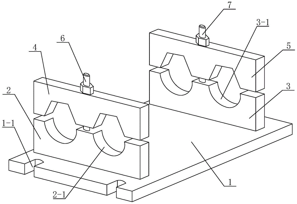
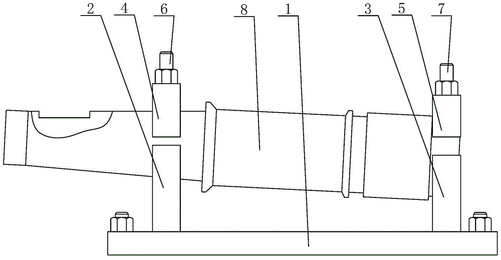
[0022] Such as figure 2 and image 3 The shown tooling fixture for processing taper shaft key grooves includes a bottom plate 1 which acts as a fixed bearing, and also includes support seat one 2 and support seat two 3 arranged in parallel for supporting the taper shaft 8, and support seat one 2 Cooperate with the V-shaped groove pressing plate one 4 for pressing the tapered shaft 8 and the V-shaped groove pressing plate two 5 for pressing the tapered shaft 8 with the support seat two 3; the support seat one 2 and the support Seat two 3 are respectively fixedly arranged on both sides of the upper part of the base plate 1, and the upper side of the support seat one 2 is provided with at least one positioning arcuate surface 2-1 having the same taper as the tapered shaft 8 tapered surface, the same taper It can ensure that the tapered surface of the tapered shaft 8 is in a horizontal position. The upper side of the support base 3 is provided with an end face positioning hole ...


PUM


Abstract

The invention discloses a tool fixture used for machining a key groove of a taper shaft. The tool fixture comprises a bottom plate, a first supporting base, a second supporting base, a first V-shaped groove pressing plate and a second V-shaped groove pressing plate, and the first supporting base and the second supporting base are arranged in parallel. The first supporting base and the second supporting base are fixedly arranged on the two sides of the upper portion of the bottom plate correspondingly. The upper side of the first supporting base is provided with at least one positioning circular-arc-shaped surface with the same taper as that of the taper surface of the taper shaft. The upper side of the second supporting base is provided with end face positioning holes used for conducting end face positioning on the taper shaft. The first V-shaped groove pressing plate is arranged on the upper side of the first supporting base. The second V-shaped groove pressing plate is arranged on the upper side of the second supporting base. The tool fixture used for machining the key groove of the taper shaft has the following characteristics of being reasonable in design, simple in structure, short in clamping time, reliable in clamping, operation is convenient and effortless, low in labor intensity, high in working efficiency, small in size, compact in structure, capable of assembling and disassembling workpieces conveniently, easy to machine, maintain and clean, low in production cost and convenient to apply and popularize.

Description

technical field [0001] The invention belongs to the technical field of mechanical processing, and relates to a simple tooling fixture, in particular to a tooling fixture for machining taper shaft key grooves. Background technique [0002] Such as figure 1 The taper shaft shown has long processing steps and high precision requirements, especially the keyway processing on the taper surface at the end of the shaft is very difficult. At present, the conventional processing method is to clamp by a vise, and use a block to support and assist positioning on the left side of the vise. By adjusting the position of the cushion block and the clamping vise, the workpiece cone surface to be processed is adjusted to the level. This processing method mainly has the following problems: 1. The clamping and calibration of the wheel axle is very difficult. The distance between the pad and the clamping place of the vise is completely controlled by the experience of the workers, and the distan...

Claims


Application Information

Patent Timeline
IPC IPC(8): B23Q3/06
Inventor 黄冰
Owner XIAN ZHIYUE ELECTROMECHANICAL TECH
Why Eureka
Try Eureka