
Microhole plate sound absorption grating

A microporous plate and sound absorption technology is applied in the field of noise reduction of range hoods, which can solve the problems of small thickness of sound-absorbing materials, reduced sound-absorbing performance, and poor sound-absorbing effect of sound-absorbing cotton, so as to achieve good sound-absorbing performance, Easy to install and remove for cleaning

Inactive Publication Date: 2016-05-18
中国船舶重工集团公司第七〇二研究所
View PDF8 Cites 2 Cited by
  • Summary
  • Abstract
  • Description
  • Claims
  • Application Information

AI Technical Summary

Problems solved by technology

The current range hood products generally use sound-absorbing cotton plus a perforated plate lining to be installed in the range hood shell as the sound-absorbing component. Since the range hood has a large amount of oil fumes and oil stains when it is in use, the surface of the sound-absorbing cotton is easily blocked by oil stains. Its sound-absorbing performance is greatly reduced, and the sound-absorbing cotton is often unable to be cleaned, and its service life is short; in addition, due to space constraints, the thickness of the sound-absorbing material that can be installed in the range hood shell is very small (generally no more than 20mm), and its The sound absorption frequency band is concentrated in the middle and high frequency bands above 1000Hz, while the noise frequency of the range hood is mainly concentrated between 500 and 2000Hz, so the sound absorption effect of the sound-absorbing cotton on the middle and low frequencies is not good.

Method used


Image

  • Microhole plate sound absorption grating
  • Microhole plate sound absorption grating
  • Microhole plate sound absorption grating

Examples


Embodiment Construction

[0018] The specific implementation manner of the present invention will be described below in conjunction with the accompanying drawings.

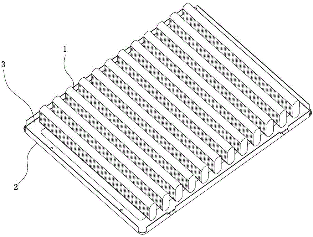
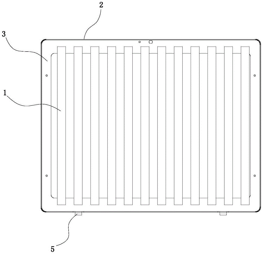
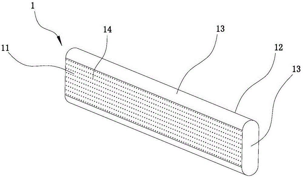
[0019] Such as figure 1 , figure 2 As shown, the microporous plate sound-absorbing grille of this embodiment includes a plurality of sound-absorbing sheets 1 installed side by side on the bottom plate 3, and the number of sound-absorbing sheets 1 is set according to the size of the range hood. In the present invention, the sound-absorbing The sheet 1 is arranged in 12 pieces; the bottom plate 3 is installed at the air inlet of the range hood through the connecting frame 2; the sound-absorbing sheet 1 is a strip-shaped cavity structure, including a microporous plate 11 and a back plate 12 on both sides, and the microporous There are side plates 13 transitionally connected between the plate 11 and the back plate 12, and the side plates 13 located on the upper and lower sides have arc-shaped curved surface structures to reduce airflow resis...


PUM

PropertyMeasurementUnit
Plate thicknessaaaaaaaaaa
Apertureaaaaaaaaaa

Abstract

The invention relates to a microhole plate sound absorption grating. The microhole plate sound absorption grating comprises a plurality of sound absorption pieces which are arranged on a bottom plate side by side, and the bottom plate is mounted on an air inlet of a smoke exhaust through a connecting frame; each sound absorption piece is of a strip-shaped cavity structure and comprises a microhole plate and a back plate which are oppositely located on the two sides, side plates are in transition connection between each microhole plate and the corresponding back plate, and the side plates at the upper end and the lower end of each sound absorption piece are provided with arc curve structures; a cavity is defined by each microhole plate, the corresponding back plate and the corresponding side plates, and micro holes are evenly distributed in each microhole plate; structural parameters of the microhole plates are designed on the basis of the Helmholtz resonator principle of small holes and the sound absorption theory of perforated plates, the plate thickness is 0.8 mm, the diameter d of the micro holes is 0.8 mm, the perforated percentage is 1%, and the cavity thickness D of the sound absorption pieces is 15 mm. The microhole plate sound absorption grating has the beneficial effects of being fireproof, good in sound absorption effect and convenient to mount, dismount and wash and preventing lampblack.

Description

technical field [0001] The invention relates to the technical field of range hoods, in particular to a noise reduction technology for range hoods. Background technique [0002] Low noise is one of the main highlights of range hood products in recent years. In addition to the low-noise design and flow diversion measures of the impeller volute system, the application of sound-absorbing materials is also a method that is gradually adopted. The current range hood products generally use sound-absorbing cotton plus a perforated plate lining to be installed in the range hood shell as the sound-absorbing component. Since the range hood has a large amount of oil fumes and oil stains when it is in use, the surface of the sound-absorbing cotton is easily blocked by oil stains. Its sound-absorbing performance is greatly reduced, and the sound-absorbing cotton is often unable to be cleaned, and its service life is short; in addition, due to space constraints, the thickness of the sound-a...

Claims


Application Information

Patent Timeline
IPC IPC(8): F04D29/66F24C15/20
Inventor 黄伟稀孙玉东邱跃统许影博何涛
Owner 中国船舶重工集团公司第七〇二研究所
Learn More