
Temperature threshold execution device and temperature monitoring system

An actuator and temperature threshold technology, applied in thermometers, measuring devices, thermometers with physical/chemical changes, etc., can solve the problems of many parts and complex structures, and achieve simple structure, large bending degree and high reliability of the device Effect

Active Publication Date: 2016-05-18
STATE GRID SHANDONG ELECTRIC POWER +1
View PDF6 Cites 0 Cited by
  • Summary
  • Abstract
  • Description
  • Claims
  • Application Information

AI Technical Summary

Problems solved by technology

[0006] Therefore, the technical problem to be solved by the present invention is to overcome the defect that the optical fiber temperature alarm threshold actuator in the prior art uses many parts and complex structure

Method used


Image

  • Temperature threshold execution device and temperature monitoring system
  • Temperature threshold execution device and temperature monitoring system
  • Temperature threshold execution device and temperature monitoring system

Examples


Embodiment 1

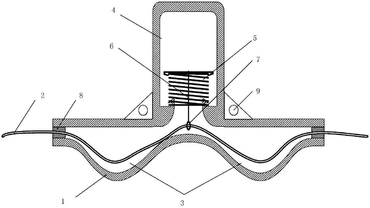
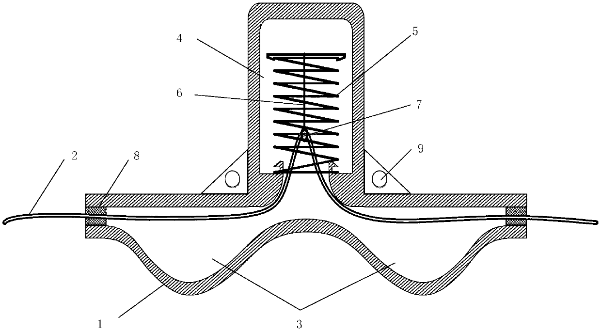
[0041] This embodiment provides a temperature threshold implementing device, which is used to increase the macrobending loss when the temperature changes, so that the loss of the optical fiber reaches a predetermined threshold and is detected. Among them, the OTDR technology combined with Rayleigh backscattering and the temperature threshold actuator of the memory alloy is an important quasi-distributed optical fiber temperature alarm system, which lays the single-mode optical fiber along the cable to be monitored. The temperature threshold actuator is placed at the cable joint). When the temperature of the monitoring point reaches the threshold temperature, the actuator will act, causing the fiber loss at this point to increase suddenly. Combined with OTDR technology, the location of the cable fault point can be quickly judged, so the system is accurate and Reliability, mainly depends on the actuator.

[0042] Based on this, a temperature threshold implementation device is pr...

Embodiment 2

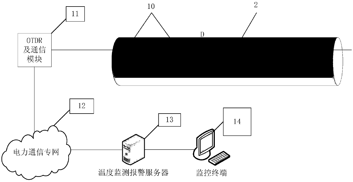
[0054] A temperature monitoring system is provided in this embodiment, such as image 3 shown, including:

[0055] One or more of the temperature threshold actuators 10 described in Embodiment 1 are installed on the optical fiber to monitor the temperature of the optical fiber at the installation position. When the temperature rises, the linkage lever 6 of the temperature threshold actuator operates to turn the optical fiber Pulling into the second chamber 4, the optical fiber produces a large bend. The optical fiber is laid in parallel along the power cable to be monitored, the optical fiber passes through the temperature threshold actuator deployed at the monitoring point, and one end of the 10 optical fiber is connected to the OTDR and the communication module 11 .

[0056] An Optical Time Domain Reflectometer (OTDR for short), connected to the optical fiber. Receive the signal in the optical fiber and generate the loss signal according to OTDR technology.

[0057] The c...


PUM


Abstract

The invention provides a temperature threshold execution device. The temperature threshold execution device comprises a first chamber and a second chamber. The first chamber is used for being penetrated through by an executed part. The second chamber is internally provided with a shape memory alloy spring. One end of the spring is fixed, and a movable end is in linkage connection with the execution part through a linkage rod. In the scheme, when a monitored environment temperature rises, the temperature of an executor rapidly rises, and once the temperature of the shape memory alloy spring reaches a transition temperature, the shape memory alloy spring extends rapidly, and at the moment, the movable end of the spring drives the executed part to move into the second chamber by means of linkage, and the executed part is enabled to generate relatively large bending, so that the loss caused by the bending is enabled to exceed a threshold, and the timely perception of the change of the monitored environment temperature is realized. The device is simple in structure, high in reliability and capable of stably working in severe environments such as wet and dust environments.

Description

technical field [0001] The invention relates to the technical field of optical fiber temperature detection, in particular to a temperature threshold execution device and a temperature monitoring system. Background technique [0002] Power cables are generally accompanied by a rise in local temperature before and during a fault. Temperature is an important parameter to reflect the operation of the cable. Therefore, monitoring the temperature of the power cable is important for monitoring the operation of the power cable and ensuring the safe operation of the power cable. means. [0003] At present, the commonly used cable temperature monitoring methods include: temperature-sensing cable temperature measurement system, thermistor temperature measurement system, distributed optical fiber temperature measurement system, etc. The distributed optical fiber temperature measurement system mainly realizes the temperature monitoring of the cable through the Raman scattering temperatu...

Claims


Application Information

Patent Timeline
IPC IPC(8): G01K11/32G01K11/322G01K11/324
CPCG01K11/32
Inventor 孟建黄彦周建波彭碧君程辉王金宇吕庆真姜正豪王红
Owner STATE GRID SHANDONG ELECTRIC POWER
Learn More