Optical repeater used for long distance seabed optical cable communication system

A submarine optical cable and optical repeater technology, which is applied in the direction of electromagnetic repeaters, etc., can solve the problems of photoelectric unit structure design, complex material selection, increased difficulty of marine construction and burial, and large volume and weight of optical repeaters. , to achieve the effect of facilitating marine construction operations, reducing the difficulty of marine construction and embedding, and reducing the difficulty of mechanical design

Active Publication Date: 2016-05-18
FIBERHOME MARINE NETWORK EQUIP CO LTD
View PDF4 Cites 8 Cited by
  • Summary
  • Abstract
  • Description
  • Claims
  • Application Information

AI Technical Summary

Problems solved by technology

[0004] Since the photoelectric unit inside the optical repeater of the traditional UC structure is an independent structure and is in direct contact with seawater, its own structure must meet the stringent requirements of watertightness, airtightness, corrosion resistance, and mechanical strength under deep-sea environmental conditions, resulting in The structural design and material selection of the photoelectric unit are relatively complicated, and the material cost is high. Therefore, the mechanical design of the photoelectric unit of the traditional UC structure optical repeater is relatively difficult, and the integrated assembly process is complicated. The resources are complex and the cost is high. The volume and weight of the optical repeater with UC structure are relatively large, which increases the difficulty of marine construction and burial, and indirectly reduces the reliability of the optical repeater.

Method used


Image

  • Optical repeater used for long distance seabed optical cable communication system
  • Optical repeater used for long distance seabed optical cable communication system
  • Optical repeater used for long distance seabed optical cable communication system

Examples


Embodiment Construction

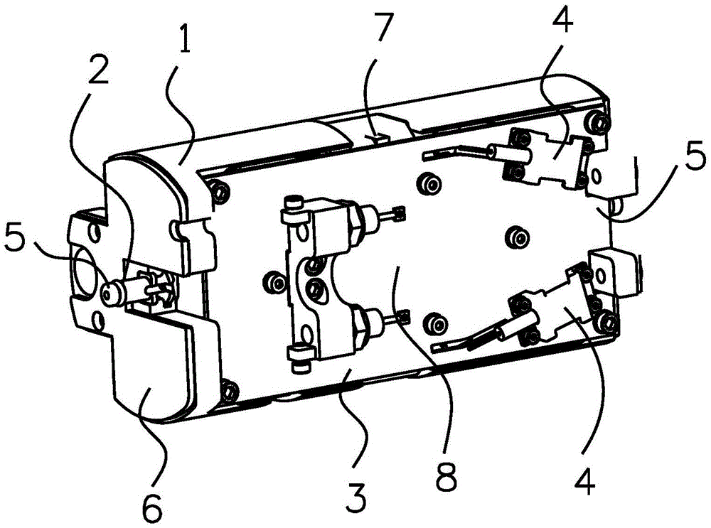
[0041] The present invention will be further described in detail below in conjunction with the accompanying drawings and specific embodiments.

[0042] An embodiment of the present invention provides an optical repeater for a long-distance submarine optical cable communication system. The optical repeater is integrated in an optimized submarine optical cable connector. The structure of the optimized submarine optical cable connector is as follows: The longitudinal center line grows and the outer diameter remains unchanged, and the optimized submarine optical cable connector is obtained, which realizes the deployment and integration of optical repeaters in the inner space of the optimized submarine optical cable connector, and the exterior of the optimized submarine optical cable connector adopts an integral injection molding process, The entire optical repeater is wrapped inside the PE (polyethylene) insulating layer and isolated from seawater.

[0043] The optical repeater in...


PUM


Abstract

The invention discloses an optical repeater used for a long distance seabed optical cable communication system, relating to the seabed optical cable communication field. The optical repeater is integrated in an optimized seabed optical cable joint; the outside of the optimized seabed optical cable joint is prepared by an overall molding process; a whole optical repeater is wrapped in a PE insulating layer, and is isolated from seawater. The optical repeater comprises a first continuous feedthrough unit, a photoelectric unit and a second continuous feedthrough unit, wherein one end of the first continuous feedthrough unit is in connection with the seabed optical cable on one side of the optical repeater, and the other end is in connection with the photoelectric unit; one end of the second continuous feedthrough unit is in connection with the photoelectric unit, and the other end is in conenciton with the optical cable on the other side of the optical repeater. According to the invention, the mechanical design difficulty of the optical repeater is reduced, integration processes and required integration matching resources are simplified, the cost is reduced, the size and weight of the optical repeater are reduced, the sea construction and burying difficulty is decreased, and the reliability is improve.

Description

technical field [0001] The invention relates to the field of submarine optical cable communication, in particular to an optical repeater used in a long-distance submarine optical cable communication system. Background technique [0002] The most important high-reliability active device in the long-distance (more than 500 kilometers) submarine optical cable communication system is the optical repeater. The long-distance submarine optical cable communication system integrates access optical repeaters within a certain span distance, and realizes the amplification and transmission of optical transmission signals in the entire submarine optical cable link. Due to the particularity of the marine environment, the long-distance submarine optical cable communication system has high requirements on the reliability of the optical repeater, and the service life of the optical repeater is generally required to exceed 25 years. In order to achieve high reliability, the optical repeater n...

Claims


Application Information

Patent Timeline
Patent Type & Authority Applications(China)
IPC IPC(8): H04B10/29
CPCH04B10/29
Inventor 周亮亮宦益国夏致宏吴军刘中华
Owner FIBERHOME MARINE NETWORK EQUIP CO LTD
Why Eureka
Try Eureka