Plunger-cylinder assembly

A component and piston technology, applied in non-mechanical drive clutches, fluid drive clutches, clutches, etc., can solve the problems of interference, troublesome construction of connecting parts of piston-cylinder components, etc., and achieve the effect of simple connection, reliable mechanical fixation and electrical connection

Active Publication Date: 2016-05-18
SCHAEFFLER TECH AG & CO KG
View PDF8 Cites 4 Cited by
  • Summary
  • Abstract
  • Description
  • Claims
  • Application Information

AI Technical Summary

Problems solved by technology

In addition, the board is susceptible to environmental influences such as vibration, temperature, and electrical interference
Additional process steps are required

Method used


Image

  • Plunger-cylinder assembly
  • Plunger-cylinder assembly
  • Plunger-cylinder assembly

Examples


Embodiment Construction

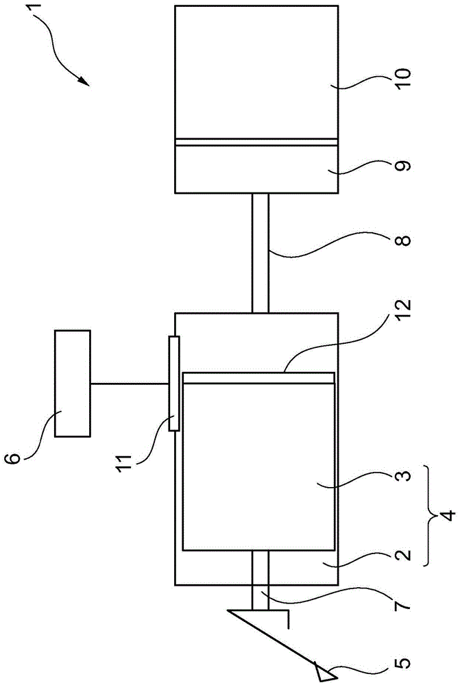
[0021] exist figure 1 A hydraulic clutch system 1 as it would be used in a motor vehicle is shown in . Such a clutch system 1 has a hydraulic actuation system in the form of a clutch master cylinder 4 , which comprises a cylinder designed as a housing 2 in which a piston 3 is mounted axially movable. The piston 3 is actuated by a clutch pedal 5 which acts on a piston rod 7 . The clutch master cylinder 4 is connected with the slave cylinder 9 for actuating the clutch 10 through a hydraulic line 8 . The adjustment of the position of the clutch 10 takes place on the basis of the actuation of the piston 3 via the clutch pedal 5 . In this case, clutch master cylinder 4 and clutch 10 with slave cylinder 9 are arranged spatially separated in the motor vehicle.

[0022] Arranged on the outside of the cylinder serving as housing 2 is an inductive sensor system 11 , opposite said inductive sensor system an electrically conductive target 12 fastened to the end face of piston 3 . The ...


PUM


Abstract

The invention relates to a plunger-cylinder assembly, in particular for a master cylinder of a clutch actuating system in a motor vehicle. The plunger-cylinder assembly comprises a plunger and a sensor system, wherein the plunger is arranged axially movably in a cylinder which is configured as a housing, and the sensor system is arranged on the housing and is operatively connected to a sensor constituent part which is fastened to the plunger. In a plunger-cylinder assembly, in which the assembly is simplified by way of a reduction in the interfaces, the sensor system is positioned on a leadframe assembly which is integrated into the plastic housing.

Description

technical field [0001] The invention relates to a piston-cylinder assembly, in particular for a master cylinder of a clutch actuating system in a motor vehicle, with a piston and a sensor system, the piston being arranged axially movable in a housing designed In the cylinder, the sensor system is arranged on the housing and is operatively connected to a sensor component fastened to the piston. Background technique [0002] In hydraulic clutch release systems used in motor vehicles, linear displacement measurement systems are used to sense the position of a piston guided in a master cylinder in order to be able to determine the actuation state of the clutch of the motor vehicle. The linear path measuring system comprises a sensor system consisting of an inductive sensor unit with a conductive target, which should also be referred to as a sensor component. Furthermore, however, it is also possible to use a Hall sensor as the sensor system which comprises a permanent magnet as...

Claims


Application Information

Patent Timeline
IPC IPC(8): F16D25/08F16D25/12
CPCF16D25/08F16D25/12F16D2025/081F16D2300/18
Inventor J·舍恩霍尔茨T·赫尔曼
Owner SCHAEFFLER TECH AG & CO KG
Why Eureka
Try Eureka