Converter bottom blowing element air-supply method conducting grouping, timing and rotary switching according to intensity

A technology of converter bottom blowing and intensity, which is applied in the field of timing, rotation and switching of gas supply, converter bottom blowing components grouped according to strength, can solve the problems of bottom blowing gas stirring kinetic energy short circuit, weakening the effect of mass transfer between slag and molten steel, etc., to increase Effective contact area and mass transfer coefficient, improvement of dead zone flow field, and good economic and technical indicators

Inactive Publication Date: 2016-05-25
CENT IRON & STEEL RES INST
View PDF7 Cites 17 Cited by
  • Summary
  • Abstract
  • Description
  • Claims
  • Application Information

AI Technical Summary

Problems solved by technology

[0011] In the blowing mode of conventional compound blowing converter with fixed bottom blowing intensity, the gas supply intensity of each bottom blowing element in a certain fixed blowing stage is generally fixed. In this blowing mode, due to the The stirring gas blown out by the components can easily cause the slag-steel interface to be blown into b...

Method used


Image

  • Converter bottom blowing element air-supply method conducting grouping, timing and rotary switching according to intensity
  • Converter bottom blowing element air-supply method conducting grouping, timing and rotary switching according to intensity
  • Converter bottom blowing element air-supply method conducting grouping, timing and rotary switching according to intensity

Examples


Embodiment 1

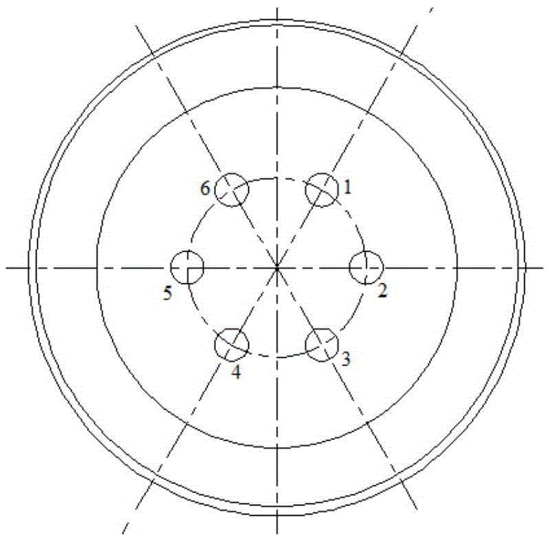
[0034] Such as figure 1 The bottom blowing element arrangement structure of a traditional compound blowing converter shown in the figure has six bottom blowing elements arranged on the bottom of the furnace, and the six bottom blowing elements are symmetrically distributed on both sides of the tapping side and distributed in a concentric circle. Divide the six bottom blowing components into two groups, among which 1, 3, and 5 odd groups form a group, and the remaining even groups form a group.

[0035] After the blowing starts, according to the actual smelting situation, the odd group can be set as the strong bottom blowing group, and the even group can be set as the weak bottom blowing group. , the bottom blowing intensity can be adjusted, the even group becomes a strong bottom blowing group, and the odd group becomes a weak bottom blowing group. During the whole smelting process, the distribution of bottom blowing intensity can be adjusted in real time according to the slag...

Embodiment 2

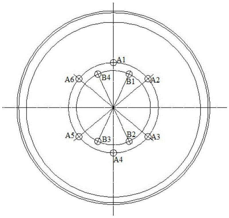
[0038] Such as figure 2 The arrangement structure of bottom blowing elements of a traditional compound blowing converter is shown. There are 10 bottom blowing elements arranged at the bottom of the furnace. The 10 bottom blowing elements are symmetrically distributed on both sides of the tapping side, but distributed in two concentric round. Divide the 10 bottom blowing components into two groups, among which group A is distributed on the outer circle, and group B is distributed on the inner circle. Group A has 6 bottom blowing components, and group B has 4 bottom blowing components. At the same time, set the odd-numbered bottom-blowing components A1, A3, and A5 of group A as strong bottom-blowing groups, and the even-numbered bottom-blowing components as weak bottom-blowing groups. Similarly, set the 4 bottom-blowing components of group B in the same way. Moreover, group A can also be uniformly set as a strong bottom blowing group, and group B can be uniformly set as a weak...

Embodiment 3

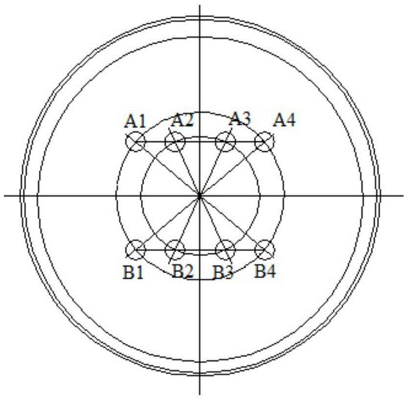
[0042] Such as image 3 The bottom-blowing components of a traditional compound-blowing converter shown are unconventional arrangement structure. There are 2 rows of 8 bottom-blowing components arranged on the bottom of the furnace, and 2 rows of 8 bottom-blowing components are symmetrically distributed on both sides of the tapping side. Divide the 8 bottom blowing components into two groups, among which the group A is distributed on the upper side, and the group B is distributed on the lower side. Group A has 4 bottom blowing components, and group B has 4 bottom blowing components. At the same time, set the odd-numbered bottom-blowing components A1 and A3 of Group A as strong bottom-blowing groups, and the even-numbered bottom-blowing components as weak bottom-blowing groups. Similarly, set the 4 bottom-blowing components of Group B in the same way. Moreover, group A can also be uniformly set as a strong bottom blowing group, and group B can be uniformly set as a weak bottom ...


PUM


Abstract

The invention discloses a converter bottom blowing element air-supply method conducting grouping, timing and rotary switching according to intensity and belongs to the technical field of converter steelmaking. According to the tonnage of a converter and the condition of the bottom of the converter, bottom blowing elements are arranged on 1-3 concentric circles of different radiuses or arranged at the bottom of the converter in a double-row or multi-row mode; the bottom blowing elements arranged on the concentric circles are numbered clockwise or anticlockwise and divided into an odd number group and an even number group according to odd numbers and even numbers of the bottom blowing elements; or the bottom blowing elements arranged in the double-row or multi-row mode are numbered from left to right according to each row and divided into an odd number group and an even number group according to odd numbers and even numbers; the bottom blowing elements in the odd number group adopt weak bottom blowing intensity, the bottom blowing elements in the even number group adopts strong bottom blowing intensity, and vice versa. On the basis of optimizing the layout of the combined-blowing converter bottom blowing elements, through the new adjusting method for grouping, timing and rotary switching of air supply intensity of all the bottom blowing elements, slag-steel interface high-efficiency continuous contact is intensified, the slag-steel interface effect contact area is increased, and the effective mass transfer coefficient is increased.

Description

technical field [0001] The invention belongs to the technical field of converter steelmaking, and in particular relates to a gas supply method in which converter bottom blowing elements are grouped according to strength, timed and rotated. Background technique [0002] With the development of China's iron and steel industry, large-scale operation has become common. Facing severe market challenges, iron and steel enterprises pay more and more attention to the improvement of product quality. As a previous process, the quality of molten steel directly affects the next process. The top-bottom combined blowing converter is widely used due to its good comprehensive smelting function. [0003] In order to further strengthen the smelting effect of the combined blowing converter, continuously improve production efficiency, reduce costs, stabilize the process, upgrade product quality, and overcome the deficiencies in the existing combined blowing technology such as partial slag materi...

Claims


Application Information

Patent Timeline
IPC IPC(8): C21C5/34
CPCC21C5/34
Inventor 曾加庆梁强吴伟杨利彬王杰刘小亮
Owner CENT IRON & STEEL RES INST
Why Eureka
Try Eureka