A preheating chemical regenerative diesel engine

A chemical recuperation, diesel engine technology, applied in mechanical equipment, engine components, combustion engines, etc., can solve the problems of low efficiency and high fuel consumption, and achieve the effects of solving solidification, improving combustion efficiency, and improving energy utilization.

Active Publication Date: 2018-06-22
HARBIN INST OF TECH
View PDF7 Cites 0 Cited by
  • Summary
  • Abstract
  • Description
  • Claims
  • Application Information

AI Technical Summary

Problems solved by technology

[0005] In order to solve the problems of low efficiency and high fuel consumption of existing diesel engines, the present invention further proposes a preheating type chemical recuperation type diesel engine

Method used


Image

  • A preheating chemical regenerative diesel engine

Examples


specific Embodiment approach 1

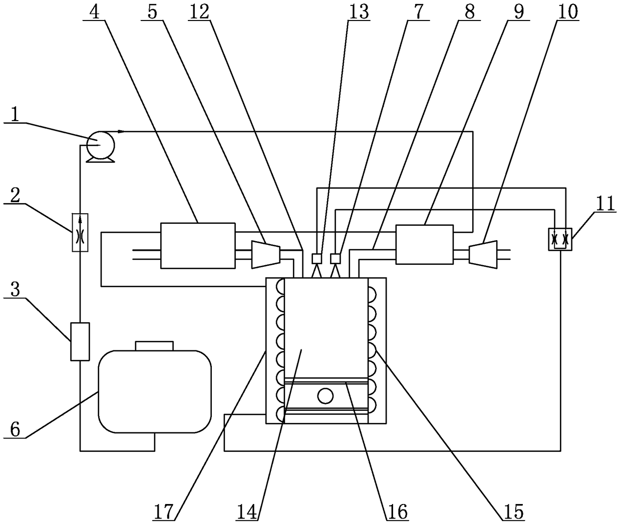
[0010] Specific implementation mode one: combine figure 1 Describe this embodiment, a preheating chemical recuperation diesel engine described in this embodiment includes a booster pump 1, a flow regulating valve 2, a diesel-exhaust gas heat exchanger 4, an exhaust gas turbine 5, an oil tank 6, and a gaseous fuel nozzle 7 , intake pipe 8, intercooler 9, supercharger 10, switching valve 11, exhaust pipe 12, liquid fuel nozzle 13, cylinder 14, cooling channel 15, piston 16 and ceramic heat insulation layer 17, the oil outlet of fuel tank 6 The port is connected to the booster pump 1 through the flow regulating valve 2, the booster pump 1 is connected to the intercooler 9, the intercooler 9 is connected to the cylinder 14 through the intake pipe 8, the piston 16 is arranged in the cylinder 14, and the cooling channel 15 is arranged in the On the outer wall of the cylinder 14, the ceramic heat insulation layer 17 is set on the cooling channel 15, the intercooler 9 is connected wit...

specific Embodiment approach 2

[0012] Specific implementation mode two: combination figure 1 To illustrate this embodiment, a preheating chemical recuperation diesel engine described in this embodiment further includes a filter 3 , and the fuel tank 6 is connected to the flow regulating valve 2 through the filter 3 . Other components and connections are the same as those in the first embodiment.

[0013] working principle

[0014] When the engine is running, the diesel oil flows out from the fuel tank 6 and passes through the filter 3. After the filter 3 filters the diesel oil, it is adjusted by the flow regulating valve 2 and then boosted by the booster pump 1. The high-pressure cold diesel oil first flows into the intercooler 9 The high-temperature air after internal cooling and supercharging enters the diesel-exhaust gas heat exchanger 4 to further absorb the waste heat of the exhaust gas; the preheated diesel oil flows into the cooling channel 15 to absorb the heat scattered by combustion into the wall...


PUM


Abstract

The invention discloses a preheating-type chemical regenerative diesel engine, and relates to a diesel engine, and in particular to the preheating-type chemical regenerative diesel engine. By using the preheating-type chemical regenerative diesel engine, the problems that an existing diesel engine is lower in efficiency and higher in oil consumption are solved. An oil outlet of an oil tank of the preheating-type chemical regenerative diesel engine is connected with a supercharge pump through a flow regulating valve; the supercharge pump is connected with an inter cooler; the inter cooler is connected with an air cylinder through an air inlet pipe; a piston is arranged in the air cylinder; a cooling passage is arranged on the outer side wall of the air cylinder; a ceramic thermal insulating layer is mounted on the cooling passage in a sleeving manner; the inter cooler is connected with a diesel oil-tail gas heat exchanger; the air cylinder is connected with an exhaust-driven gas turbine through an exhaust pipe; the exhaust-driven gas turbine is connected with the diesel oil-tail gas heat exchanger; the air cylinder is connected with a switching valve; the switching valve is connected with the air cylinder through a gaseous fuel nozzle and a liquid fuel nozzle; the supercharge pump is connected with the inter cooler. The preheating-type chemical regenerative diesel engine belongs to the field of internal combustion engines.

Description

technical field [0001] The invention relates to a diesel engine, in particular to a preheating chemical recuperation diesel engine, which belongs to the field of internal combustion engines. Background technique [0002] The internal combustion engine is currently the most commonly used form of power, and its exhaust gas is one of the important reasons for the greenhouse effect and air pollution. Among them, diesel engines widely used in trucks, buses, ships, tractors and railway locomotives are regarded by the public as "accomplices" of smog due to their low efficiency and substandard emissions in daily use. At the same time, the ever-increasing demand for oil consumption not only increases the environmental burden of our country, but also increases the international political and military pressure to maintain oil trade. Therefore, it is extremely urgent to improve the efficiency of diesel engines and reduce fuel consumption and exhaust emissions. [0003] As we all know,...

Claims


Application Information

Patent Timeline
Patent Type & Authority Patents(China)
IPC IPC(8): F02B69/04F02M37/00F02M31/16F02M31/14F02M27/00
CPCF02B69/04F02M27/00F02M31/14F02M31/16F02M37/0047
Inventor 秦江程昆林鲍文张铎
Owner HARBIN INST OF TECH
Why Eureka
Try Eureka